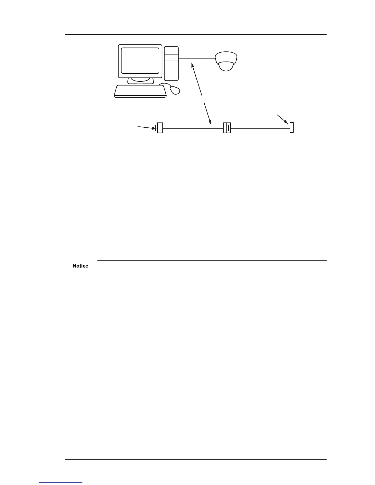
Figure 17: Serial port connection
4. On the PC, use a Terminal Emulation program such as Windows HyperTerminal and
set the serial port parameters as follows:
• 115200 baud
• 8 bits
• No parity
• 1 stop bit
• Flow Control: None
5. If using an auxiliary PSU, connect the power supply.
► For more information, see "Auxiliary power" on page 20
► For more information about pinout details, see "Wiring requirements" on page 14
6. Switch on the auxiliary power supply to apply power to the camera, or, if using Power
over Ethernet, plug in the network cable.
Please allow 45 seconds for the camera to boot up.
7. Connect to the device and press Enter. Log in to the device using the default
credentials. You should see the prompt.
• Use DHCP (y/n) — Enter y to use DHCP for IP configuration, or n for manual IP
configuration.
• IP Address — Enter the IP address of the device.
• Subnet Mask — Enter the IP network subnet mask.
• Default Gateway — Enter the appropriate default gateway for remote network access.
This is only required if the devices are to be accessed from a different subnet.
• Host name — Enter a name to describe the device.The name can only contain
alphanumerical characters and hyphens.
• Location — Enter a name to describe the location of the device. The location can only
contain alphanumerical characters and hyphens.
• Link type — Enter a link type. The values are as follows:
• 0 - 10Mbps Half-Duplex
• 1 - 10Mbps Full-Duplex
• 2 - 100Mbps Half-Duplex
• 3 - 100Mbps Full-Duplex
• 4 - Auto-negotiate
Enhanced SDFixed Dome - 9000 Range 3 Getting Started