Figure 26: Invert the center of grommet to create a collar around the cable
Only use the cable to pierce the grommet. Do not use any other tools, for example, a
screwdriver or scalpel. If you use your own cable, ensure it has a round cross-section.
Alternatively, a round section cable of diameter 5-10mm can be used. Push the cable
through the center of the grommet to make a hole and then terminate the cable with an
RJ45 connector.
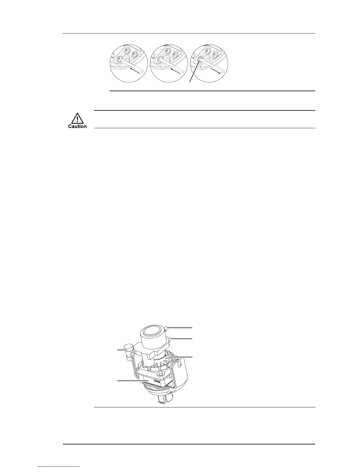
Fit the camera to the Exit Collar
When you have connected the camera, fit the Camera Assembly to the Exit Collar.
1. Ensure that the adhesive backed gasket is attached to the Exit Collar (9).
2. Connect the cables to the Camera Assembly (6) as required.
3. Connect the earth strap between the Exit Collar and the Camera Assembly using the
connection points provided.
4. Place the desiccant bag securely in the Exit Collar.
5. Fix the Camera Assembly to the Exit Collar by aligning the notch on the plastic base
plate with the key on the exit collar.
6. Secure the Camera Assembly to the Exit Collar using the three Security Screws (7)
and drive bit provided.
To ensure a watertight seal, tighten the security screws to a minimum of 15 Nm (11
lbs/ft) and maximum of 20 Nm (15 lbs/ft).
Setting up the sensor
When you are setting up the sensor, you can view analog video output on a video monitor.
This can be accessed by connecting the supplied analog video cable to the 2-way flying
connector within the camera.