iNetVu
®
Mobile Installation Manual Page 42 of 93
i. Ensure that the Ball Joint Stud faces outwards (away from the centre of the
Reflector).
ii. Verify holes on the reflector (mounting bracket side) have been counter sunk
otherwise the flat head screws will not be flush with the Mounting bracket once
installed.
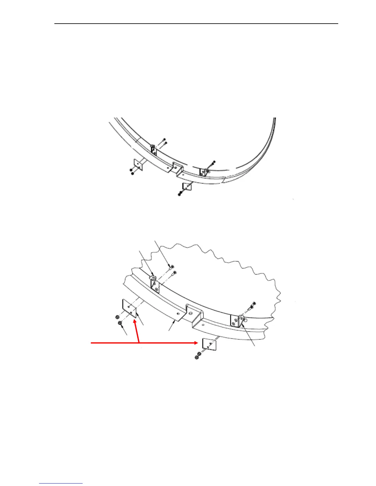
iii. Align the backing plates on the back of the reflector with the mounting holes of
the gas spring brackets as depicted in Fig 23. and Fig 24.
iv. Insert and tighten the two (2) lower screws closest to reflector edge.
Fig. 24: Correct Gas Spring Bracket Orientation
Fig. 25: Backing plate location