iNetVu
®
Mobile Installation Manual Page 46 of 93
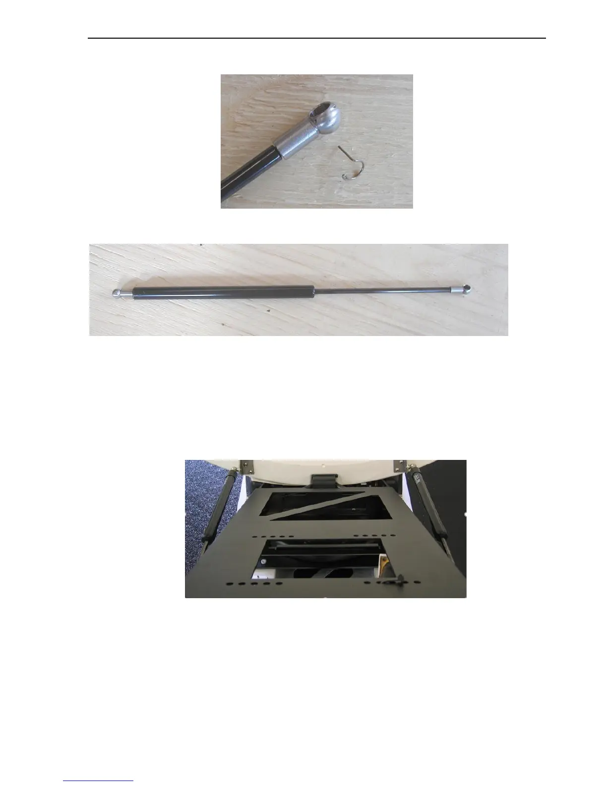
13. Remove the clips from the Ball Joints at the ends of the Gas Springs and place aside.
Fig. 30: Removed Clip from Ball Joints
Fig. 31: Gas Shock Spring
14. Snap-on the thicker end of the Gas Spring to the Reflector’s Gas Spring Brackets.
Once this end is snapped into place, re-insert clip.
15. By hand, compress the Gas Spring, and snap-on the thinner end of the Gas Spring to
the Gas Spring Brackets on the Mobile Platform. Once this end is snapped into place,
re-insert clip.
Fig. 32: Assembled Gas Spring Assembly
16. Repeat Steps 12 and 13 for both Gas Springs.
17. Congratulations! The 1.2m Reflector has been successfully installed on to an iNetVu®
1200 Mobile Platform.