TLE5012B
Application Circuits
User’s Manual 18 Rev. 1.2, 2018-02
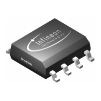
3.3 HSM interface and SSC (HSM in open-drain configuration)
As shown in Figure 3-3 when IFA, IFB and IFC are configurated via the SSC interface as open drain pins, three
pull-up resistors (Rpu) should be added on the output lines.
Figure 3-3 Application circuit for TLE5012B with HSM interface (open-drain configuration) and SSC
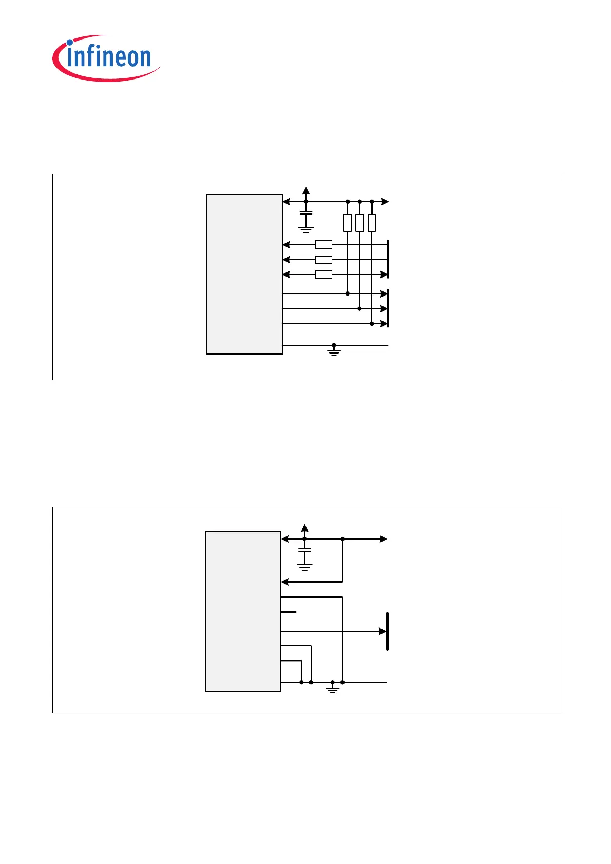
3.4 PWM interface (push-pull configuration)
The TLE5012B can be configured with PWM only (Figure 3-4). The derivate TLE5012B - E5000 is by default
configurated with push-pull configuration for IFA (PWM) pin. Internal pull-up resistors are always available for
DATA and CSQ pins (see Datasheet). It is recommended to connect CSQ pin to V
DD
to provide a high level and
avoid unintentional activation of the SSC interface. DATA pin should be left open. The figure below shows a typical
implementation of the TLE5012B - E5000.
Figure 3-4 Application circuit for TLE5012B with PWM (push-pull configuration) interface
TLE5012B
CSQ
SCK
DATA
IFA
IFB
IFC
GND
VDD
3.0 – 5.5V
Rs1
SSC
HSM
100nF
(HS1)
(HS2)
(HS3)
Rs1
Rs2
Rs1 recommended, e.g. 100
Rs2 recommended, e.g. 470
Rpu
Rpu
Rpu
Rp u req uir ed, e.g. 2K2
TLE5012B
CSQ
SCK
DATA
IFA
IFB
IFC
GND
VDD
3.0 – 5.5V
100nF
(PWM)
Rpd recommended, e.g. 10k
PWM