TLE5012B
Application Circuits
User’s Manual 21 Rev. 1.2, 2018-02
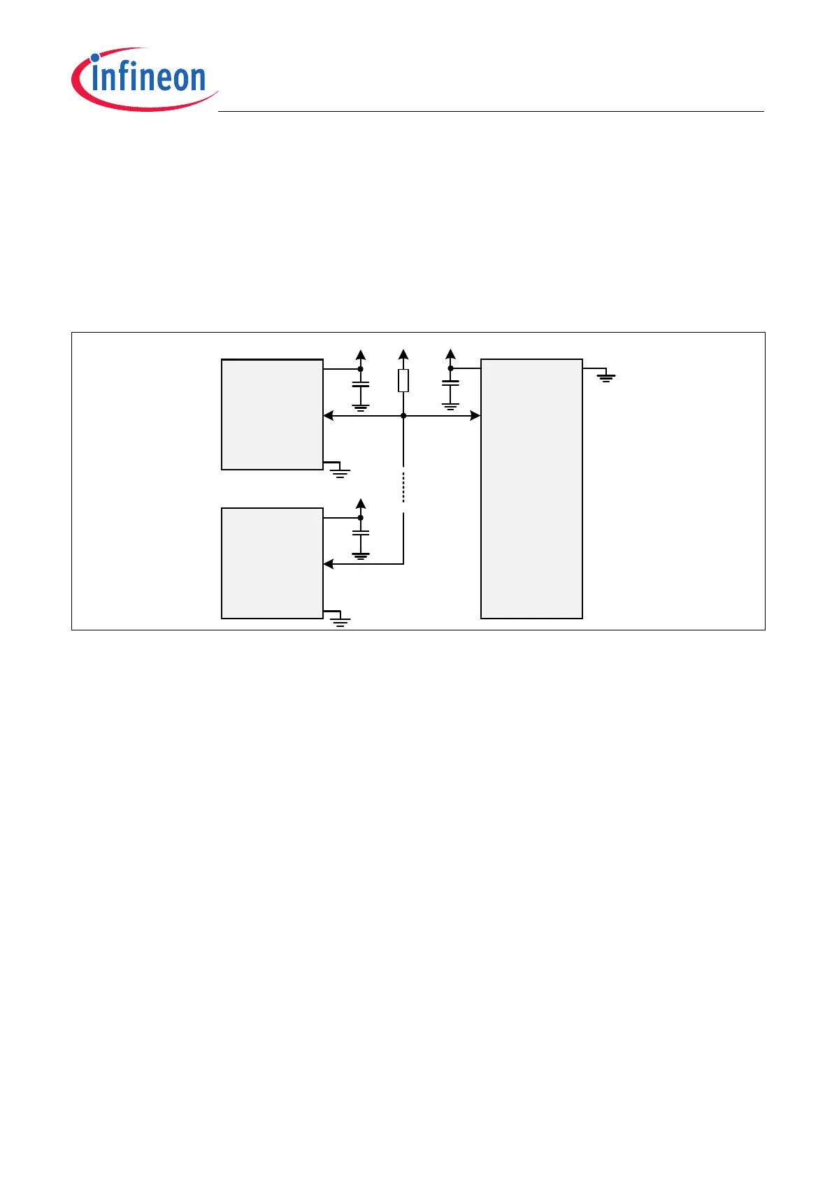
3.9 Sensor supply in bus mode
When using two or more devices in a bus configuration (SSC or SPC interface). It is recommended to use the
same supply for every sensors connected to the bus. In case of a power loss the unpowered device is sinking
current through the OUT pin. Depending on the external circuitry the additional current flow might disturb the bus
behavior.
The figure below (Figure 3-9) shows a typical implementation of a bus mode using SPC interface. External
components such as EMC filter or additional series resistors are not represented for clarity purpose. Only the pull-
up resistor Rpu is shown.
Figure 3-9 Sensors’ supply in bus mode
Sensor 1
OUT
VDD
VDD
CCU
VDD
GND
VDD
GND
MCU
VDD
Rpu
VDD
Sensor x
OUT
VDD
GND