TLE5012B
Interfaces
User’s Manual 51 Rev. 1.2, 2018-02
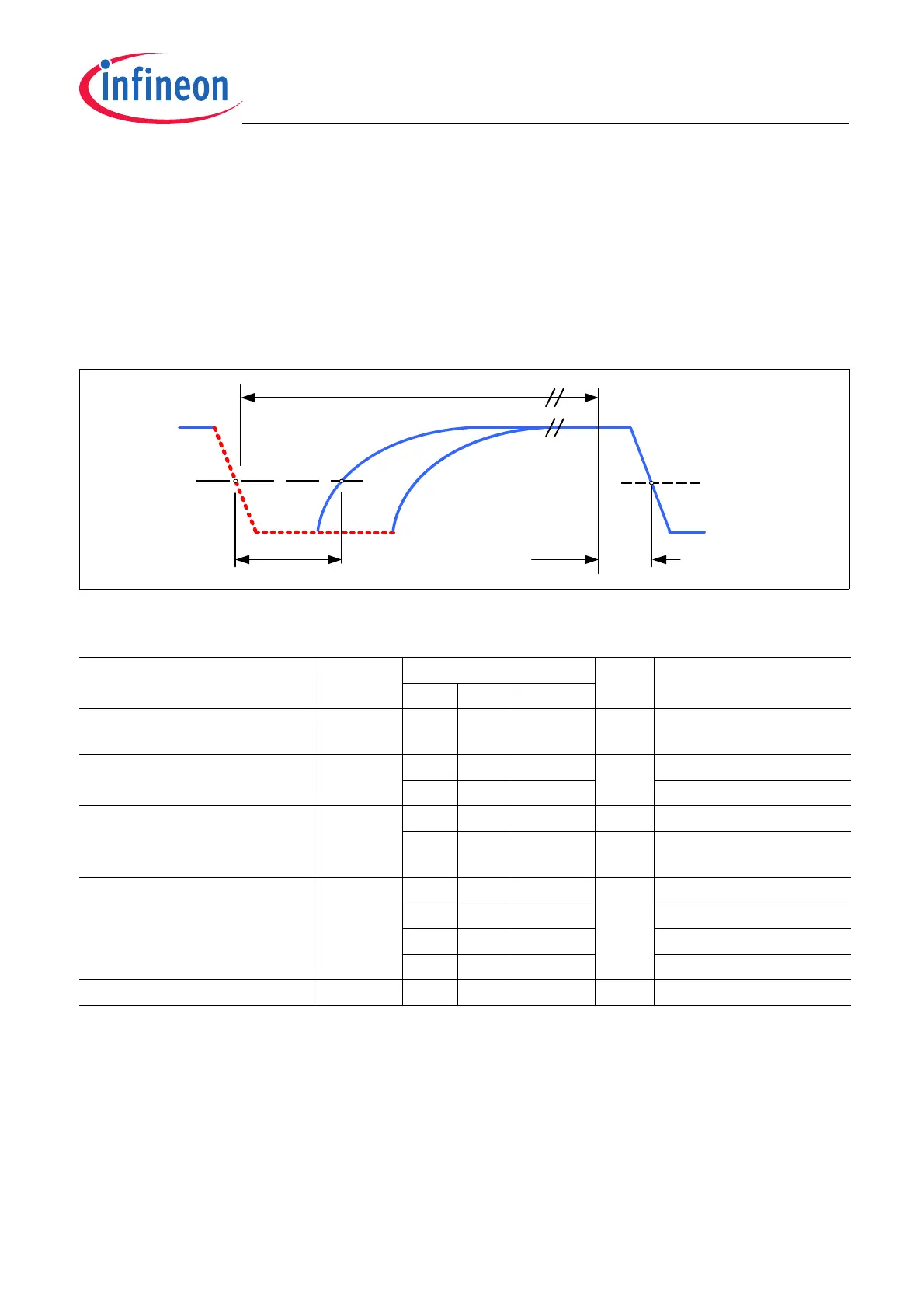
5.4.2 Master Trigger Pulse Requirements
An SPC transmission is initiated by a master trigger pulse on the IFA pin. To detect a low-level on the IFA pin, the
voltage must be below a threshold V
th
. The sensor detects that the IFA line has been released as soon as V
th
is
crossed. Figure 5-16 shows the timing definitions for the master pulse. The master low time t
mlow
as well as the
total trigger time t
mtr
are given in Table 5-11.
If the master low time exceeds the maximum low time, the sensor does not respond and is available for a next
triggering 30 μs after the master pulse crosses V
thr
. t
md,tot
is the delay between internal triggering of the falling edge
in the sensor and the triggering of the ECU.
Figure 5-16 SPC Master pulse timing
Total trigger time
The SPC_Trigger is set to 0 by default. For a variable-length SPC Trigger Nibble -and therefore an overall shorter
SPC Frame- the SPC_Trigger bit can be set to 1 via the SSC interface. The SPC_Trigger bit is the second MSB
of the HSM_PLP bits of the MOD_4 register (address 0E
H
). Check Chapter 6.2 for further details.
Table 5-11 Master pulse parameters
Parameter Symbol Values Unit Note / Test Condition
Min. Typ. Max.
Threshold
V
th
50 % of
V
DD
1)
1) Not subject to production test - verified by design/characterization
Threshold hysteresis V
thhyst
8% ofV
DD
= 5 V
1)
3V
DD
V
DD
= 3 V
1)
Total trigger time t
mtr
90 UT SPC_Trigger = 0;
1)2)
2) Trigger time in the sensor is fixed to the number of units specified in the “typ.” column, but the effective trigger time varies
due to the sensor’s clock variation
t
mlow
+12
UT SPC_Trigger = 1
1)
Master low time t
mlow
8 12 14 UT S_NR =00
1)
16 22 27 S_NR =01
1)
29 39 48 S_NR =10
1)
50 66 81 S_NR =11
1)
Master delay time t
md,tot
5.8 μs
1)
SPC
ECU trigger
level
V
th
t
mlow
t
md,tot
t
mtr