TLE5012B
Interfaces
User’s Manual 46 Rev. 1.2, 2018-02
5.3 Pulse Width Modulation Interface
The Pulse Width Modulation (PWM) interface can be selected via SSC (IF_MD = ‘01’) in the register MOD_4.
The PWM update rate can be programmed within the register 0E
H
(IFAB_RES) in four possible steps with 12-bit
resolution (including diagnostics):
• ~0.25 kHz
• ~0.5 kHz
• ~1.0 kHz
• ~2.0 kHz
PWM uses a square wave with constant frequency whose duty cycle is modulated according to the last measured
angle value (AVAL register).
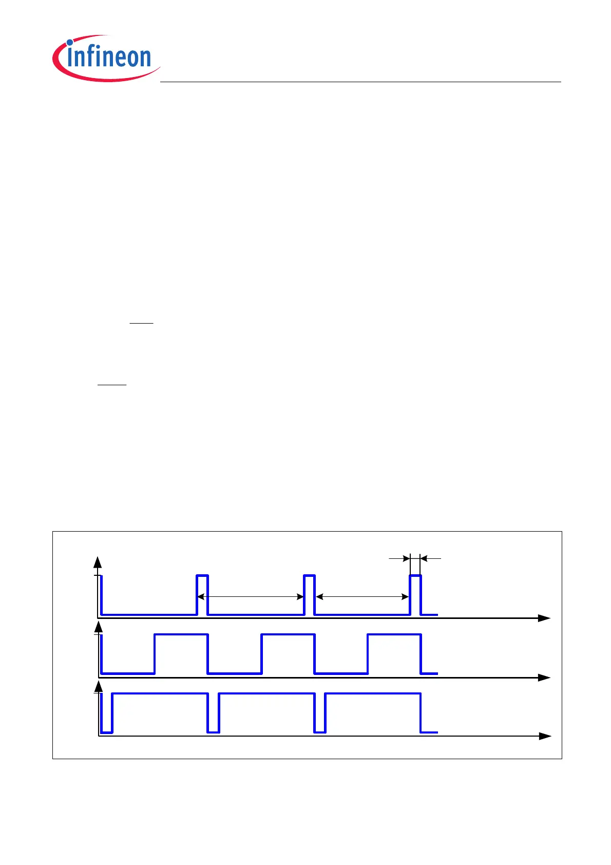
Figure 5-11 shows the principal behavior of a PWM with various duty cycles and the definition of timing values.
The duty cycle of a PWM is defined by the following general formulas:
(5.6)
The duty cycle range between 0 - 6.25% and 93.75 - 100% is used only for diagnostic purposes. In case the sensor
detects an error, the corresponding error information will be transmitted by the PWM duty cycle, either in the lower
(0 - 6.25%) or upper (93.75 - 100%) diagnostic range, depending on the kind of error (see “Output duty cycle
range” in Table 5-7). As long as a fault is present, the error information will be transmitted in PWM frames. This
diagnostic function can be disabled via the MOD_4 register (see Chapter 6.2).
Sensors with preset PWM are available as TLE5012B E5xxx. The register settings for these sensors can be found
in Chapter 6.2.
Figure 5-11 Typical example of a PWM signal
PWM
PWM
offonPWM
PWM
on
t
f
ttt
t
t
CycleDuty
1
=
+=
=
t
ON
‚0'
t
ON = High level OFF = Low level
Duty cycle = 6.25%
Duty cycle = 50%
Duty cycle = 93.75%
t
PWM
t
OFF
Vdd
U
IFA
Vdd
U
IFA
t
‚0'
t
Vdd
U
IFA
‚0'