TLE5012B
Interfaces
User’s Manual 55 Rev. 1.2, 2018-02
5.5 Hall Switch Mode (HSM)
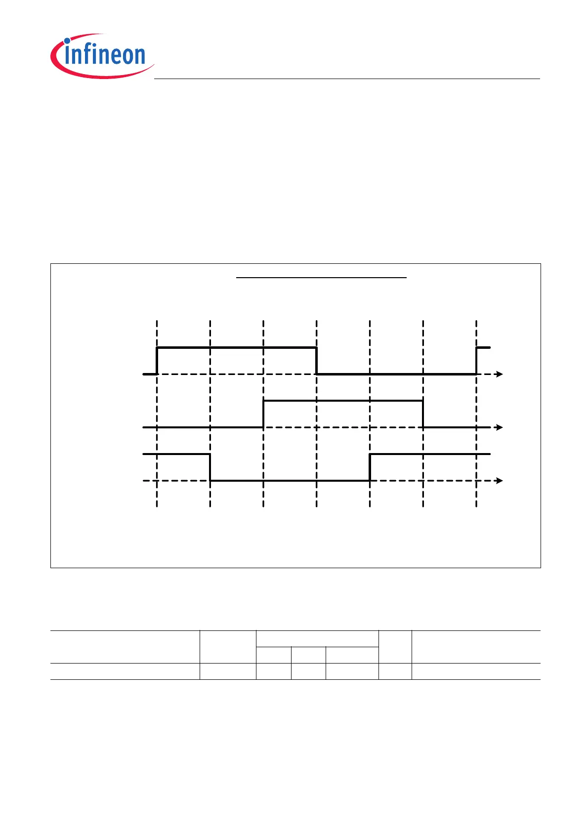
The Hall Switch Mode (HSM) within the TLE5012B makes it possible to emulate the output of 3 Hall switches. Hall
switches are often used in electrical commutated motors to determine the rotor position. With these 3 output
signals, the motor will be commutated in the right way. Depending on which pole pairs of the rotor are used, various
electrical periods have to be controlled. This is selectable within 0E
H
(HSM_PLP). Figure 5-19 depicts the three
output signals with the relationship between electrical angle and mechanical angle. The mechanical 0° point is
always used as reference.
The HSM is generally used with push-pull output, but it can be changed to open-drain within the register IFAB_OD.
Sensors with preset HSM are available as TLE5012B E3xxx. The register settings for these sensors can be found
in the Chapter 6.2.
Figure 5-19 Hall Switch Mode
The HSM Interface can be selected via SSC (IF_MD = 010).
Table 5-12 Hall Switch Mode
Parameter Symbol Values Unit Note / Test Condition
Min. Typ. Max.
Rotation speed n 10000 rpm Mechanical
2)
HS1
HS2
HS3
0°Electrical Angle 60° 120° 180° 240° 300° 360°
Hall-Switch-Mode: 3phase Generation
Angle
Mech. Angle with
5 Pole Pairs
0° 12° 24° 36° 48° 60° 72°
0° 20° 40° 60° 80° 100° 120°
Mech. Angle with
3 Pole Pairs