TLE5012B
Application Circuits
User’s Manual 20 Rev. 1.2, 2018-02
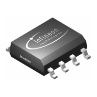
3.7 SSC interface (push-pull configuration)
In Figure 3-1, Figure 3-2 and Figure 3-3 the SSC interface has the default push-pull configuration (see details in
Figure 3-7). A series resistor on the DATA line is recommended to limit the current in erroneous cases (e.g. the
sensor pushes high and the microcontroller pulls low at the same time or vice versa). Resistors on SCK and CSQ
lines are recommended in case of disturbances or noise.
Figure 3-7 SSC interface with push-pull configuration (high-speed application)
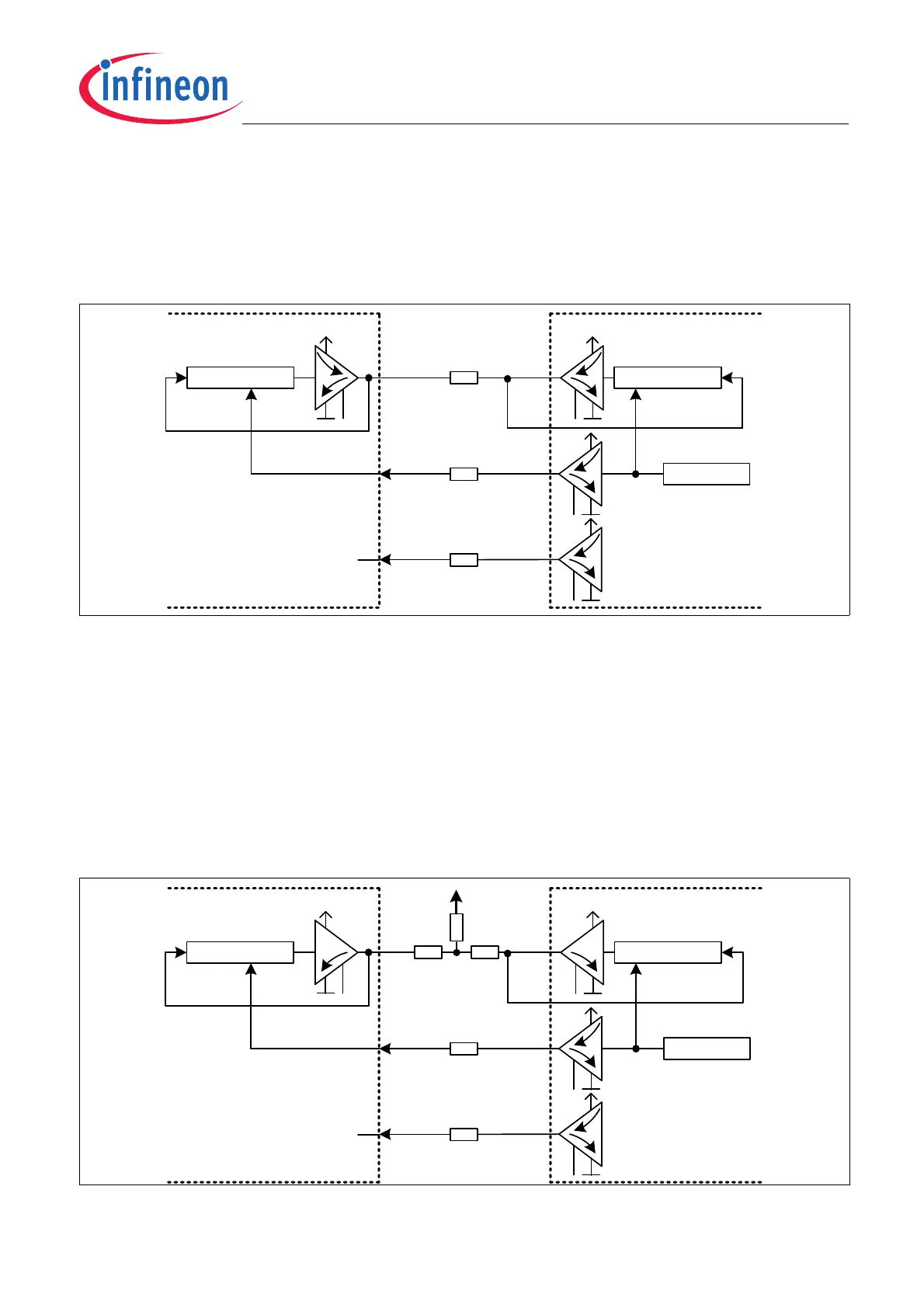
3.8 SSC interface (open-drain configuration)
It is possible to use an open-drain configuration for the DATA line. This setup can be used to communicate with a
microcontroller in a bus system, together with other SSC slaves (e.g. two TLE5012B devices for redundancy
reasons). This mode can be activated using the bit SSC_OD.
Even though, push-pull configuration in a bus system is also possible since the addressing of the sensor is
perfomed with CSQ pin.
The open-drain configuration can be seen in Figure 3-8. Series resistors on the DATA line are recommended to
limit the current in erroneous cases. Resistors on SCK and CSQ lines are recommended in case of disturbances
or noise A pull-up resistor of typ. 1 kΩ is required on the DATA line.
Figure 3-8 SSC interface with open-drain configuration (bus systems)
Shift Reg.
Shift Reg.
Clock Gen.
DATA
MTSR
MRST
SCK
SCK
(SSC Slave) TLE 5012B µC (SSC Master)
CSQ CSQ
EN
EN
Rs1 recommended, e.g. 100
Rs2 recommended, e.g. 470
Rs1
Rs1
Rs2
Shift Reg.
Shift Reg.
Clock Gen.
DATA
MTSR
MRST
SCK
SCK
(SSC Slave) TLE 5012B µC (SSC Master)
CSQ CSQ
Rs1 recommended, e.g. 100
Rpu required, e.g. 1k
Rs1
Rs1
Rs1 Rs1
Rpu
EN
EN