TLE5012B
Interfaces
User’s Manual 36 Rev. 1.2, 2018-02
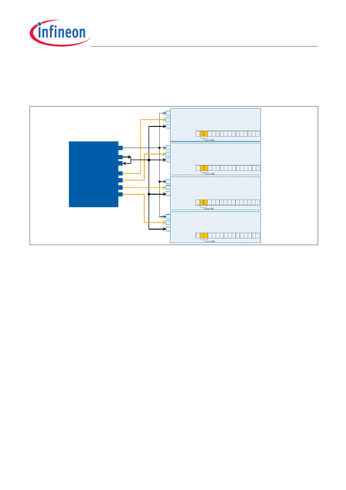
5.2.3 TLE5012B in bus mode
Up to four slaves can be connected on the same bus (e.g. four TLE5012B, or two TLE5012B and two Linear Hall).
The master microcontroller (µC) will need four CSQ (chip select) pins to connect to each of the slaves (Daisy Chain
schemes are not possible).
Figure 5-6 Example of four slaves connected to a bus with one master with SSC interface
The TLE5012B particularity is that it is a 3-pin SSC (SPI) slave. One of these pins is for the Clock, another one is
for the Chip Select and the third one is for the Data (input and output). Since there is only one pin for the Data, the
output and input of the master have to be connected. When the sensor transmits data the master’s output pin
(SDO pin) has to be switched to high ohmic.
Clock generation
As described in Chapter 5.2.1 the master has to send a command word to start the communication between
master and slave. After that, the master has to trigger a clock so the slave can respond with the data and/or safety
word. To generate a clock set the direction of the master’s SDO pin to input and next write 0xFFFF in the SDO
register. A delay t
wr_delay
(see Table 5-2) has to be implemented before generating the clock for the answer.
With this a pulse of “1s” is generated and the clock triggered. Since the SDO has been set as an input pin, this
pulse of “1s” will not be transmitted and will not interefere with the data coming from the slave (sensor). This step
(writing 0xFFFF) has to be repeated as many times as reads from the slave are expected. This is usually twice;
one for the data and one for the safety word.
Slave Number configuration at start-up
With SSC the CSQ line ensures that the data sent -or received- goes to -or comes from- the correct slave. Still, if
the slave number (S_NR bits) are not configurated correctly at start-up, the safety word may report a wrong slave
number. The slave number may also be wrong in configurations with one single slave.
To ensure that the received slave number in the safety word is correct (RESP bits), configure the slave numbers
at start up with a write command. The slave number bits are described in the Status Register.
For configurations with only one or two slaves, it is also possible to configure the slave number at start up with the
SCK and IFC pins as done for the SPC interface (see Figure 5-12). The particularity with SSC interface is that the
SCK is a line connected to the master and therefore can only have on status at start-up. Setting the IFC pin at
“high” or “low” two slave numbers can be configurated.
SPI
master
(µC)
SCK
SDI
CSQ
0
CSQ
1
CSQ
2
CSQ
3
SPI
slave 1
(TLE5012B)
SCK (pin #2)
CSQ (pin #3)
Data (pin #4)
SPI
slave 4
(TLE5012B)
SCK (pin #2)
CSQ (pin #3)
Data (pin #4)
SPI
slave 3
(TLE5012B)
SCK (pin #2)
CSQ (pin #3)
Data (pin #4)
SPI
slave 2
(TLE5012B)
SCK (pin #2)
CSQ (pin #3)
Data (pin #4)
x01xxxxxxxxxxxxx
x00xxxxxxxxxxxxx
x10xxxxxxxxxxxxx
x11xxxxxxxxxxxxx
STAT
(Status Register)
S_NR bits
STAT
(Status Register)
S_NR bits
STAT
(Status Register)
S_NR bits
STAT
(Status Register)
S_NR bits
SDO