TLE5012B
Interfaces
User’s Manual 47 Rev. 1.2, 2018-02
The PWM frequency is derived from the digital clock via
(5.7)
The min/max values given in Table 5-7 take into account the internal digital clock variation specified in TLE5012B
Data Sheet. If external clock is used, the variation of the PWM frequency can be derived from the variation of the
external clock using Equation (5.7).
Pulse length convertion to angle value
The length of the duty cycle represents the angle value. Whatever the absolute angle value is, the t
on
time depends
on the angle value calculated by the TLE5012B with resolution up to 0.100°. The 0.100° resolution is due to the
fact that with 12bit resolution (4096 steps) 100% of the duty cycle can be mapped, but only 87.5% of the duty cycle
translates to angle values. This means that the 360° degees must be mapped with only 3584 steps (87.5%*4096),
so effective resolution is 0.100°.
The angle value can be measured with the following formula, where t
ON
is the length of the pulse in seconds and
f
PWM
is the frequency selected:
(5.8)
The frequency for the PWM interface can be selected via the register MOD_4 (IFAB_RES bits) as described in
Chapter 6.2.1. See Chapter 7 for the PWM derivates with the default frequencies.
A t
ON
of more than 93.75% duty cycle would indicate an error as described in Table 5-7.
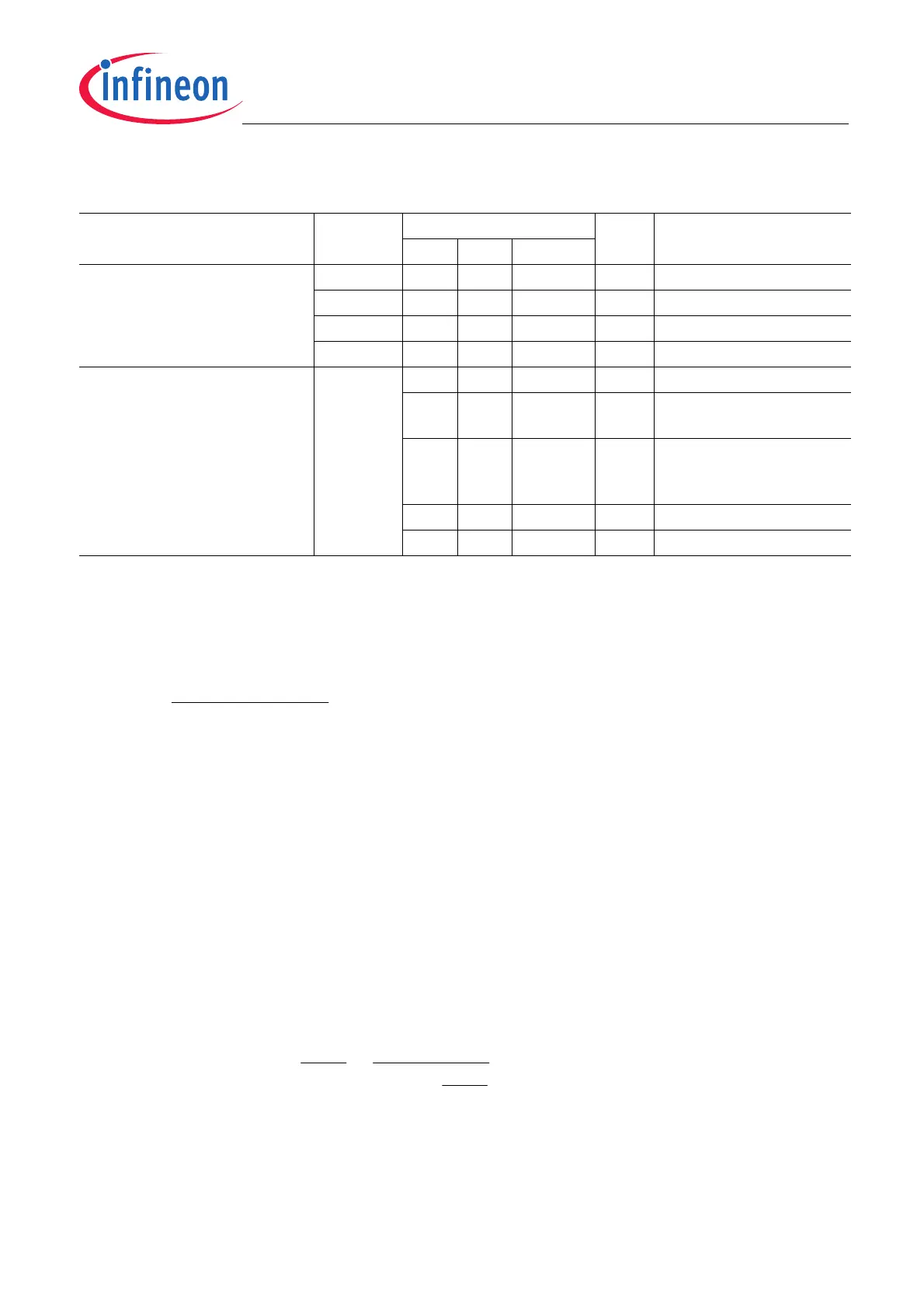
Table 5-7 PWM interface
Parameter Symbol Values Unit Note / Test Condition
Min. Typ. Max.
PWM output frequencies
(Selectable by IFAB_RES)
f
PWM1
232 244 262 Hz
1)
1) Not subject to production test - verified by design/characterization
f
PWM2
464 488 525 Hz
1)
f
PWM3
929 977 1050 Hz
1)
f
PWM4
1855 1953 2099 Hz
1)
Output duty cycle range DY
PWM
6.25 93.75 % Absolute angle
1)
2 % Electrical Error (S_RST;
S_VR)
1)2)
2) Both hardware and software resets will generate an Electrical Error duty cycle for the first PWM pulse after the reset
(S_RST). After readout, S_RST bit will be set to “0”, so the second PWM pulse will indicate an angle.
98 % System error (S_FUSE;
S_OV; S_XYOL;
S_MAGOL; S_ADCT)
1)
0 1 % Short to GND
1)
99 100 % Short to V
DD
, power loss
1)
4096*24
PWM
PWM
ON
f
f
tAngle
1
*%5.87
360
*
1
*%25.6][
°
⎟
⎟
⎠
⎞
⎜
⎜
⎝
⎛
−=°