TLE5012B
Specification
User’s Manual 25 Rev. 1.2, 2018-02
4.1.1 Angle Error adder with Autocalibration enabled
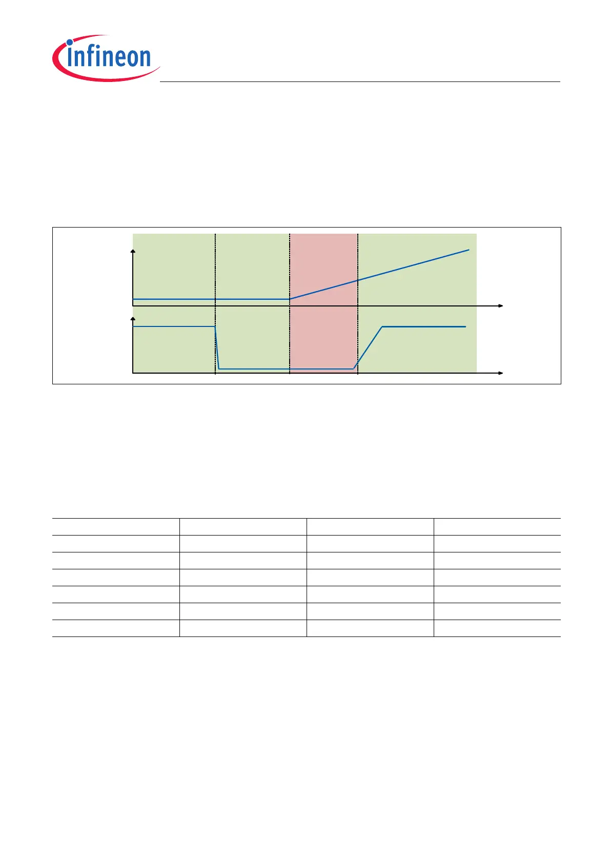
With constant temperatures (ΔT < 5 Kelvin) or parts rotating faster than the temperature changes, the
autocalibration angle error is as specified in the TLE5012B Data Sheet. If autocalibration is enabled when the
temperature changes by more than 5 Kelvin within 1.5 revolutions, the last valid autocalibration parameters will
still be used, leading to an additional angle error. Such cases will happen when the rotating part is halted and the
temperature is changing by more than 5 Kelvin or the rotating part is moving too slowly compared to the external
temperature changes (see Figure 4-4).
Figure 4-4 Cases where an angle error adder has to be included if autocalibration is enabled
The angle error adder is described in the TLE5012B Data Sheet (Figure 4-3, page #25 on the TLE5012B Data
Sheet, Rev. 2.0 from 2014-02) and depends on the initial temperature. To read the right angle error adder select
the initial temperature and move through the x-axis as many degrees as the delta between the final temperature
and the initial temperature. Then read the y-axis value at this delta and add it to the specified angle error, which
already contains lifetime drifts. Some cases are shown in Table 4-2:
As the magnetic field decreases with higher temperatures, angle errors due to increases of temperature are more
critical than decreases of temperature. As the additional angle error described in the TLE5012B Data Sheet
applies to the worst case (temperature increasing), the angle error adder due to decreasing temperature changes
will always be smaller.
If a parallel SSC interface is in place, autocalibration can be disabled when a critical case described in Figure 4-4
occurs. A temperature check in the microcontroller can be implemented to disable and enable autocalibration (and
thus to reset any wrong minima and maxima) on temperature changes by more than 5 Kelvin during 1.5
revolutions. When autocalibration is disabled the default calibration parameters stored in the laser fuses will be
used for the X and Y raw values correction, and the angle error will fulfill the specifications described in the
TLE5012B Data Sheet.
Table 4-2 Additional angle error examples
T
junction
range Autocal T/1.5 revolutions Additional angle error
-40°C ... 150°C Off - No additional angle error
-40°C ... 150°C On < 5 Kelvin No additional angle error
-40°C ... 150°C On 10 Kelvin <0.2°
-40°C ... 150°C On 20 Kelvin <0.35°
-40°C ... 150°C On 50 Kelvin <0.85°
>135°C On 15 Kelvin <3.3°
T
rpm
Additional
Angle Error
OKOK OK