TLE5012B
Interfaces
User’s Manual 61 Rev. 1.2, 2018-02
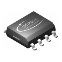
Figure 5-24 Increcremental Interface startup pulses frequency
IIF Index
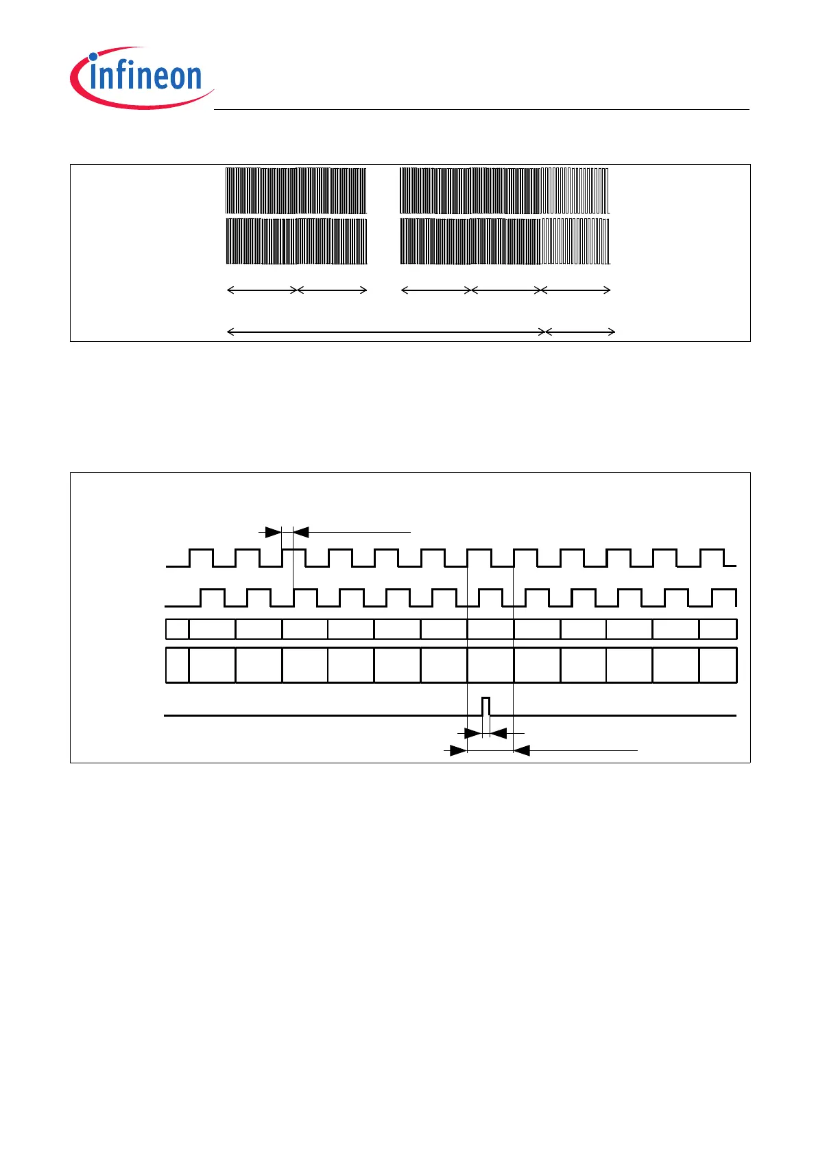
The IFC pin -or IIF Index- generates one pulse at zero crossing. This output can be used as check or as
comparison with the Phase A/Phase B outputs. The IIF Index pulse will be generated when the internal
Incremental Interface Counter steps over 0°. The IIF Index pulse width (t
0°
) duration is specified in Table 5-13.
Figure 5-25 IIF Index pulse in A/B Mode
t
upd
…
…
Phase B
Phase A
t
upd
t
upd
t
upd
t
upd
Maximum frequency (1MHz)
Remaining
pulses
90° el. Phase shift
Phase A
Phase B
Incremental Interface
(A/B Mode)
V
H
V
L
V
H
V
L
Index
V
H
V
L
t
0°
Index pulse timing
...
Counter
12LSB
4090 4091 4092 4093 4094 4095 0 1 2 3 4 ...
...
IIF_CNT
14LSB
16360...
16363
16364...
16367
16368...
13671
16372...
16375
16376...
16379
16380...
16383
0...3 4...7 8...11 12...15 16...19 ...