Thermal/Mechanical Reference Design
18 Dual-Core Intel® Xeon® Processor 5100 Series Thermal/Mechanical Design Guide
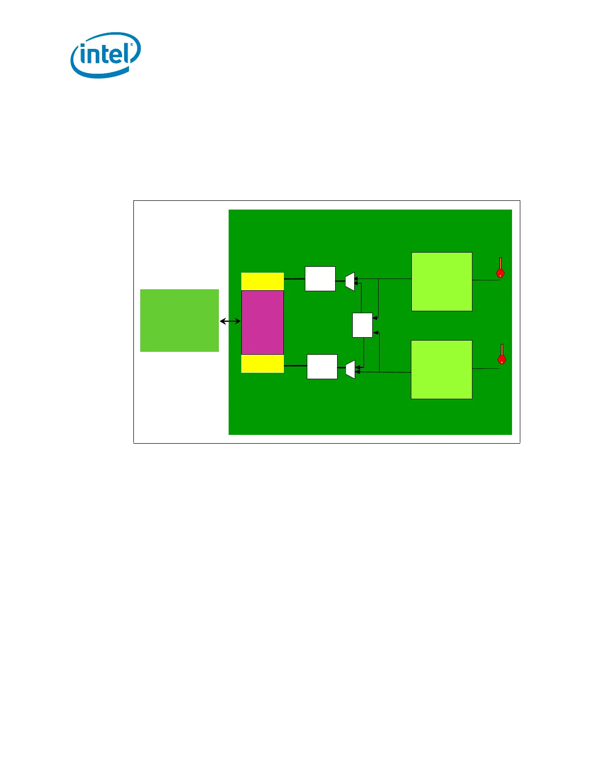
2.2.4.3 Fan Speed Control for Dual-Core Intel Xeon Processor 5100 Series
There is only one pin (Pin G5) on each LGA771 socket that accesses the single domain
of the Dual-Core Intel Xeon Processor 5100 Series. Through this pin, the single domain
receives all temperature sensor values and provides the current hottest value to an
external PECI device such as a thermal management system. Figure 2-3 provides an
illustration of the fan speed signals for the multiple core Dual-Core Intel
®
Xeon
®
Processor 5100 Series.
The processor MSR supports temperature threshold interrupts and provides
instantaneous data. To reduce the sample rate requirements on PECI and improve
thermal data stability vs. time, the processor Digital Thermal Sensor and PECI interface
implement an averaging algorithm. For more information on the Processor Thermal
Data Sample Rate and Filtering, please refer to Dual-Core Intel
®
Xeon
®
Processor
5100 Series Datasheet.
2.2.4.4 PROCHOT#, THERMTRIP#, and FORCEPR#
The PROCHOT# and THERMTRIP# outputs will be shared by all cores on a processor.
The first core to reach TCC activation will assert PROCHOT#. A single FORCEPR# input
will be shared by each core. Table 2-2 provides an overview of input and output
conditions for the Dual-Core Intel Xeon Processor 5100 Series thermal management
features.
Figure 2-3. Fan Speed Control for Dual-Core Intel Xeon Processor 5100 Series
LPF
LPF
MAX
Core 1
DTS Logic
Core 2
DTS Logic
PECI
Digital temp MSR Core 1
FSC
Digital temp MSR Core 2
Temperature
Averaging
Temperature
Averaging
LPF
LPF
MAX
Core 1
DTS Logic
Core 2
DTS Logic
PECI
FSC
Temperature
Averaging
Temperature
Averaging
LPF
LPF
MAX
Core 1
DTS Logic
Core 2
DTS Logic
PECI
Digital temp MSR Core 1
FSC
Digital temp MSR Core 2
Temperature
Averaging
Temperature
Averaging
LPF
LPF
MAX
Core 1
DTS Logic
Core 2
DTS Logic
PECI
FSC
Temperature
Averaging
Temperature
Averaging