Thermal/Mechanical Reference Design
22 Dual-Core Intel® Xeon® Processor 5100 Series Thermal/Mechanical Design Guide
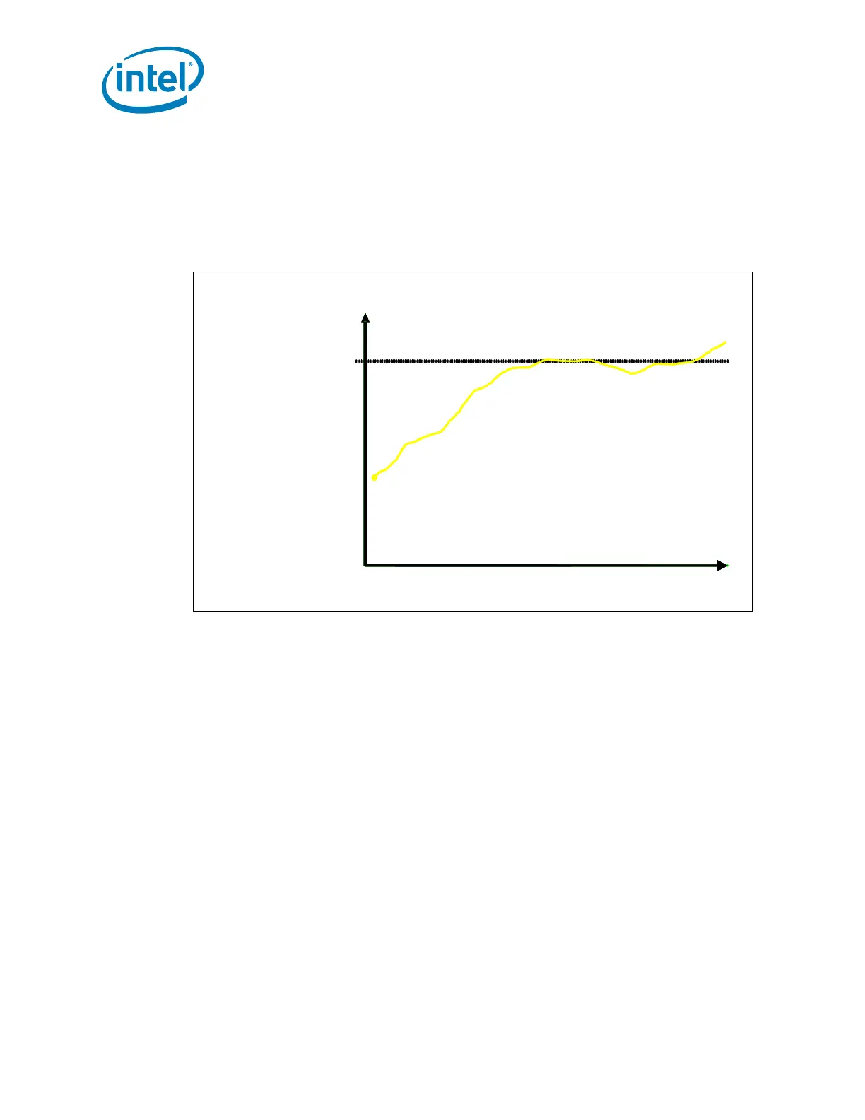
2.2.6 T
CONTROL
Definition
T
CONTROL
can be described as a trigger point for fan speed control implementation. The
processor T
CONTROL
value is now a DTS value. Because the temperatures provided by
the Digital Thermal Sensor are relative and no longer absolute, the T
CONTROL
value is
now defined as a relative value to the TCC activation set point (that is, 0°C). Figure 2-6
depicts the interaction between the T
CONTROL
value and Digital Thermal Sensor value.
The value for T
CONTROL
is calibrated in manufacturing and configured for each processor
individually. For the Dual-Core Intel Xeon Processor 5100 Series, the T
CONTROL
value is
obtained by reading a processor model specific register (MSR). NOTE: There is no
T
CONTROL_BASE
value to sum as previously required on legacy processors. The fan speed
control device only needs to read the T
OFFSET
MSR and compare this to the DTS value
from the PECI interface. The equation for calculating T
CONTROL
is:
Equation 2-2.T
CONTROL
= -T
OFFSET
Where:
T
OFFSET
= A DTS-based value programmed into each processor during
manufacturing that can be obtained by reading the IA32_TEMPERATURE_TARGET
MSR. This is a static and a unique value. Refer to the RS - Conroe and Woodcrest
Processor Family BIOS Writer’s Guide for further details.
Figure 2-7 depicts the interaction between the Thermal Profile and T
CONTROL
.
Figure 2-6. T
CONTROL
Value and Digital Thermal Sensor Value Interaction
-30
-20
-10
0
-40
Time
Digital Thermal Sensor Temperature
Tcontrol = -5
Temperature
-30
-20
-10
0
-40
-30
-20
-10
0
-40
Time
Digital Thermal Sensor Temperature
Tcontrol = -5
Temperature