Thermal/Mechanical Reference Design
38 Dual-Core Intel® Xeon® Processor 5100 Series Thermal/Mechanical Design Guide
If other custom heatsinks are intended for use with the Dual-Core Intel
®
Xeon
®
Processor 5100 Series, they must support the following interface control requirements
to be compatible with the reference mechanical components:
• Requirement 1: Heatsink assembly must stay within the volumetric keep-in.
• Requirement 2: Maximum mass and center of gravity.
Current maximum heatsink mass is 1000 grams [2.2 lbs] and the maximum center of
gravity 3.81 cm [1.5 in.] above the bottom of the heatsink base.
• Requirement 3: Maximum and minimum compressive load.
Any custom thermal solution design must meet the loading specification as
documented within this document, and should refer to the Dual-Core Intel
®
Xeon
®
Processor 5100 Series Datasheet and LGA771 Socket Mechanical Design Guide and for
specific details on package/socket loading specifications.
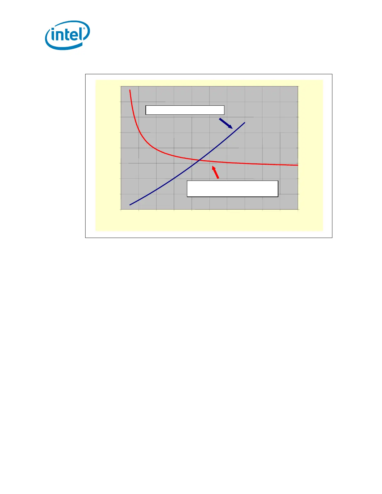
Figure 2-15. 2U+ CEK Heatsink Thermal Performance
0.05
0.10
0.15
0.20
0.25
0.30
0.35
0.40
0.45
0 102030405060708090100
CFM Through Fins
Ψ
ca
, C/W
0.00
0.10
0.20
0.30
0.40
0.50
0.60
0.70
0.80
Δ
P, inch water
Mean
Ψ
ca
= 0.1811 + 1.2872*CFM
-0.9998
σ
= 0.0024 C/W
Δ
P = 3.75e-05CFM
2
+ 5.71e-03CFM
0.05
0.10
0.15
0.20
0.25
0.30
0.35
0.40
0.45
0 102030405060708090100
CFM Through Fins
Ψ
ca
, C/W
0.00
0.10
0.20
0.30
0.40
0.50
0.60
0.70
0.80
Δ
P, inch water
Mean
Ψ
ca
= 0.1811 + 1.2872*CFM
-0.9998
σ
= 0.0024 C/W
Δ
P = 3.75e-05CFM
2
+ 5.71e-03CFM