Thermal/Mechanical Reference Design
48 Dual-Core Intel® Xeon® Processor 5100 Series Thermal/Mechanical Design Guide
The fan outputs a SENSE signal, an open-collector output, which pulses at a rate of two
pulses per fan revolution. A baseboard pull-up resistor provides VCC to match the
baseboard-mounted fan speed monitor requirements, if applicable. Use of the SENSE
signal is optional. If the SENSE signal is not used, pin 3 of the connector should be tied
to GND.
It is recommended that a 4 pin fan header be used on the baseboard, in addition to, a
control ASIC that can send a PWM signal to the active fan heatsink solution on the 4
th
pin, at a nominal 25 KHz frequency. If a 3-pin CPU fan header is used instead, the
active fan heatsink solution will revert back to an automatic ambient air temperature
control mode.
The fan power header on the baseboard must be positioned to allow the fan heatsink
power cable to reach it. The fan power header identification and location must be
documented in the supplier’s platform documentation, or on the baseboard itself. The
baseboard fan power header should be positioned within 177.8 mm [7 in.] from the
center of the processor socket.
Note: System board should pull this pin up to V
CC
with a resistor.
2.4.8.2 Systems Considerations Associated with the Active CEK
This heatsink was designed to help pedestal chassis users to meet the processor
thermal requirements without the use of chassis ducting. It may be necessary to
implement some form of chassis air guide or air duct to meet the T
LA
temperature of 40
° C depending on the pedestal chassis layout. Also, while the active heatsink solution is
designed to mechanically fit into a 2U chassis, it may require additional space at the
top of the heatsink to allow sufficient airflow into the heatsink fan. Therefore, additional
Table 2-10. Fan Specifications (Boxed 4-wire PWM/DTS Heatsink Solution)
Description Min
Typ
Steady
Max
Steady
Max
Startup
Unit Notes
+12V: 12 Volt Fan Power
Supply
10.8 12 12 13.2 V
IC: Fan Current Draw N/A 1.25 1.5 1.5 A
SENSE: SENSE Frequency 2 2 2 2 Pulses per fan revolution 1
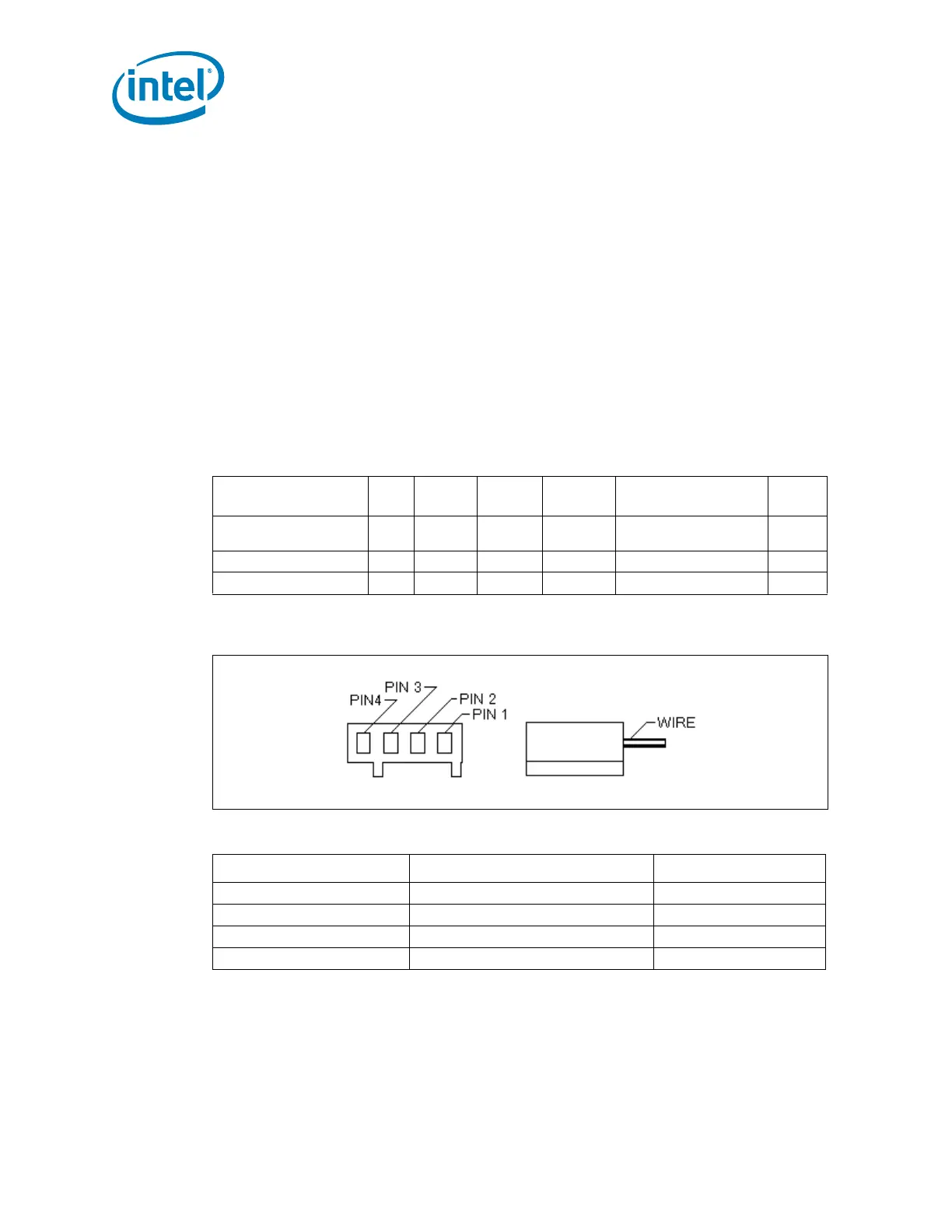
Figure 2-26. Fan Cable Connection (Active CEK)
Table 2-11. Fan Cable Connector Pin Out (Active CEK)
Pin Number Signal Color
1 Ground (Constant) Black
2 Power (+12 V) Yellow
3 Signal: 2 pulses per revolution Green
4 Control 21 KHz - 28 KHz Blue