Thermal/Mechanical Reference Design
44 Dual-Core Intel® Xeon® Processor 5100 Series Thermal/Mechanical Design Guide
Note: Refer to Appendix A for more detailed mechanical drawings of the heatsink.
The function of the standoffs is to provide a bridge between the chassis and the
heatsink for attaching and load carrying. When assembled, the heatsink is rigid against
the top of the standoff, and the standoff is rigid to a chassis standoff with the CEK
spring firmly sandwiched between the two. In dynamic loading situations the standoff
carries much of the heatsink load, especially in lateral conditions, when compared to
the amount of load transmitted to the processor package. As such, it is comprised of
steel. The distance from the bottom of the heatsink to the bottom of the standoff is
10.26 mm [0.404 in.] for a board thickness of 1.57 mm [0.062 in]. The standoff will
need to be modified for use in applications with a different board thickness, as defined
in Section 2.4.4.2.
The function of the screw is to provide a rigid attach method to sandwich the entire CEK
assembly together, activating the CEK spring under the baseboard, and thus providing
the TIM preload. A screw is an inexpensive, low profile solution that does not negatively
impact the thermal performance of the heatsink due to air blockage. Any fastener (i.e.
head configuration) can be used as long as it is of steel construction; the head does not
interfere with the heatsink fins, and is of the correct length of 20.64 mm [0.8125 in.].
Although the CEK heatsink fits into the legacy volumetric keep-in, it has a larger
footprint due to the elimination of retention mechanism and clips used in the older
enabled thermal/mechanical components. This allows the heatsink to grow its base and
fin dimensions, further improving the thermal performance. A drawback of this
enlarged size and use of copper for both the base and fins is the increased weight of
the heatsink. The retention scheme employed by CEK is designed to support heavy
heatsinks (approximately up to 1000 grams) in cases of shock, vibration and
installation as explained in Appendix D. Some of the thermal and mechanical
characteristics of the CEK heatsinks are shown in Table 2-8.
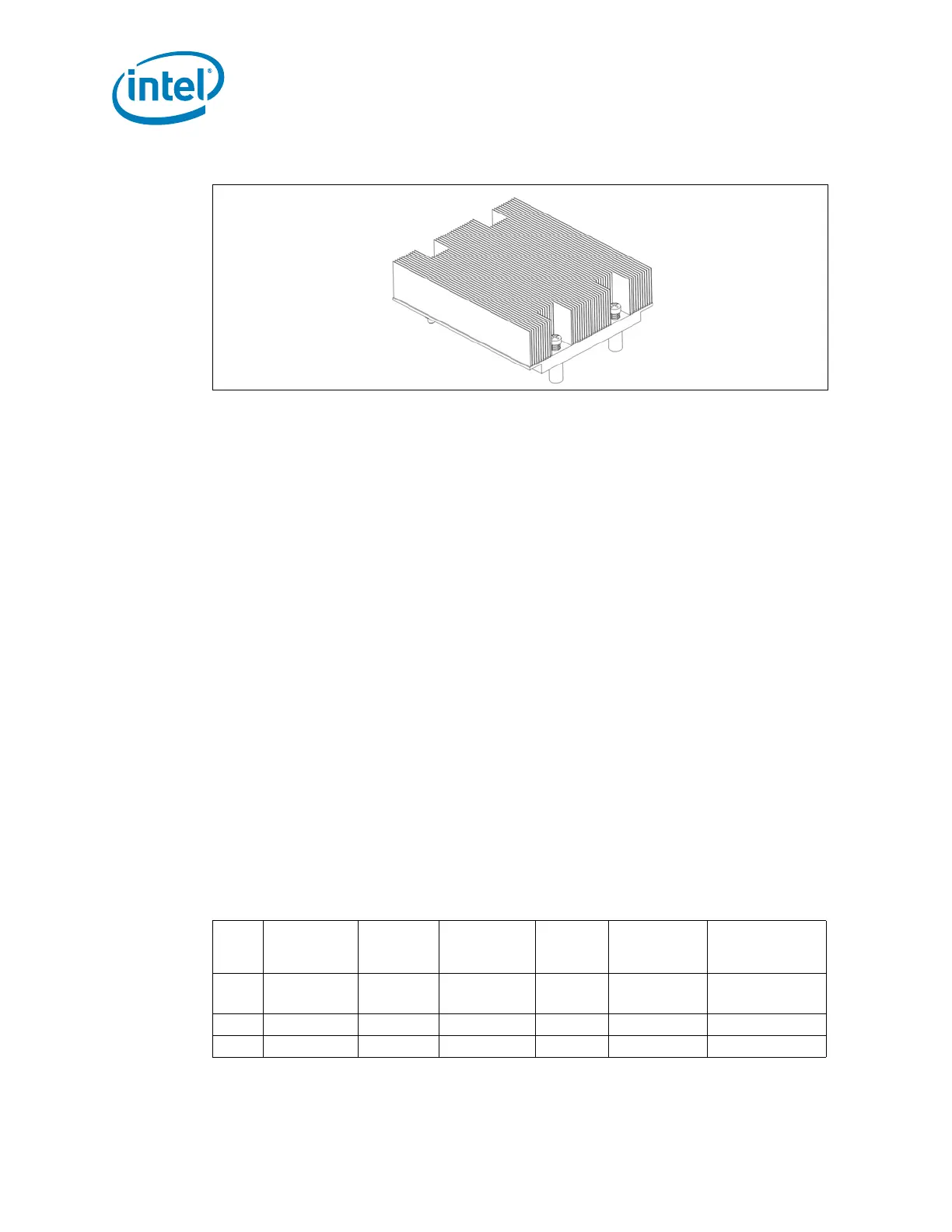
Figure 2-22. Isometric View of the 1U CEK Heatsink
Table 2-8. CEK Heatsink Thermal Mechanical Characteristics
Size
Height Weight
Target
Airflow
Through Fins
Mean Ψ
ca
Standard
Deviation Ψ
ca
Pressure Drop
(mm) [in.] (kg) [lbs]
(m
3
/hr)
[CFM]
(° C/W) (° C/W) (Pa) [in H
2
O]
2U+ 50.80 [2.00] 1.0 [2.2] 45.9 [27] 0.229 0.0024 45.3 [0.182]
1U 27.00 [1.06] 0.53 [1.2] 25.5 [15] 0.290 0.0028 82.4 [0.331]