Dual-Core Intel® Xeon® Processor 5100 Series Thermal/Mechanical Design Guide 51
Mechanical Drawings
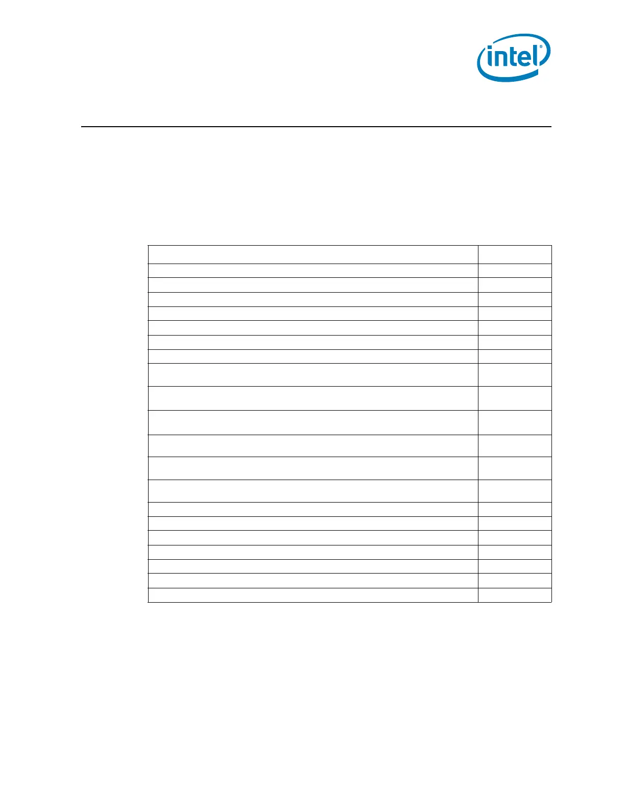
A Mechanical Drawings
The mechanical drawings included in this appendix refer to the thermal mechanical
enabling components for the Dual-Core Intel Xeon Processor 5100 Series.
Note: Intel reserves the right to make changes and modifications to the design as necessary.
Table A-1. Mechanical Drawing List
Drawing Description Figure Number
“2U CEK Heatsink (Sheet 1 of 4)” Figure A-1
“2U CEK Heatsink (Sheet 2 of 4)” Figure A-2
“2U CEK Heatsink (Sheet 3 of 4)” Figure A-3
“2U CEK Heatsink (Sheet 4 of 4)” Figure A-4
“CEK Spring (Sheet 1 of 3)” Figure A-5
“CEK Spring (Sheet 2 of 3)” Figure A-6
“CEK Spring (Sheet 3 of 3)” Figure A-7
“Baseboard Keepout Footprint Definition and Height Restrictions for Enabling Components
(Sheet 1 of 6)”
Figure A-8
“Baseboard Keepout Footprint Definition and Height Restrictions for Enabling Components
(Sheet 2 of 6)”
Figure A-9
“Baseboard Keepout Footprint Definition and Height Restrictions for Enabling Components
(Sheet 3 of 6)”
Figure A-10
“Baseboard Keepout Footprint Definition and Height Restrictions for Enabling Components
(Sheet 4 of 6)”
Figure A-11
“Baseboard Keepout Footprint Definition and Height Restrictions for Enabling Components
(Sheet 5 of 6)”
Figure A-12
“Baseboard Keepout Footprint Definition and Height Restrictions for Enabling Components
(Sheet 6 of 6)”
Figure A-13
“1U CEK Heatsink (Sheet 1 of 4)” Figure A-14
“1U CEK Heatsink (Sheet 2 of 4)” Figure A-15
“1U CEK Heatsink (Sheet 3 of 4)” Figure A-16
“1U CEK Heatsink (Sheet 4of 4)” Figure A-17
“Active CEK Thermal Solution Volumetric (Sheet 1 of 3)” Figure A-18
“Active CEK Thermal Solution Volumetric (Sheet 2 of 3)” Figure A-19
“Active CEK Thermal Solution Volumetric (Sheet 3 of 3)” Figure A-20