Setting Up the Chassis
Intel® Server Chassis SC5300 User Guide 15
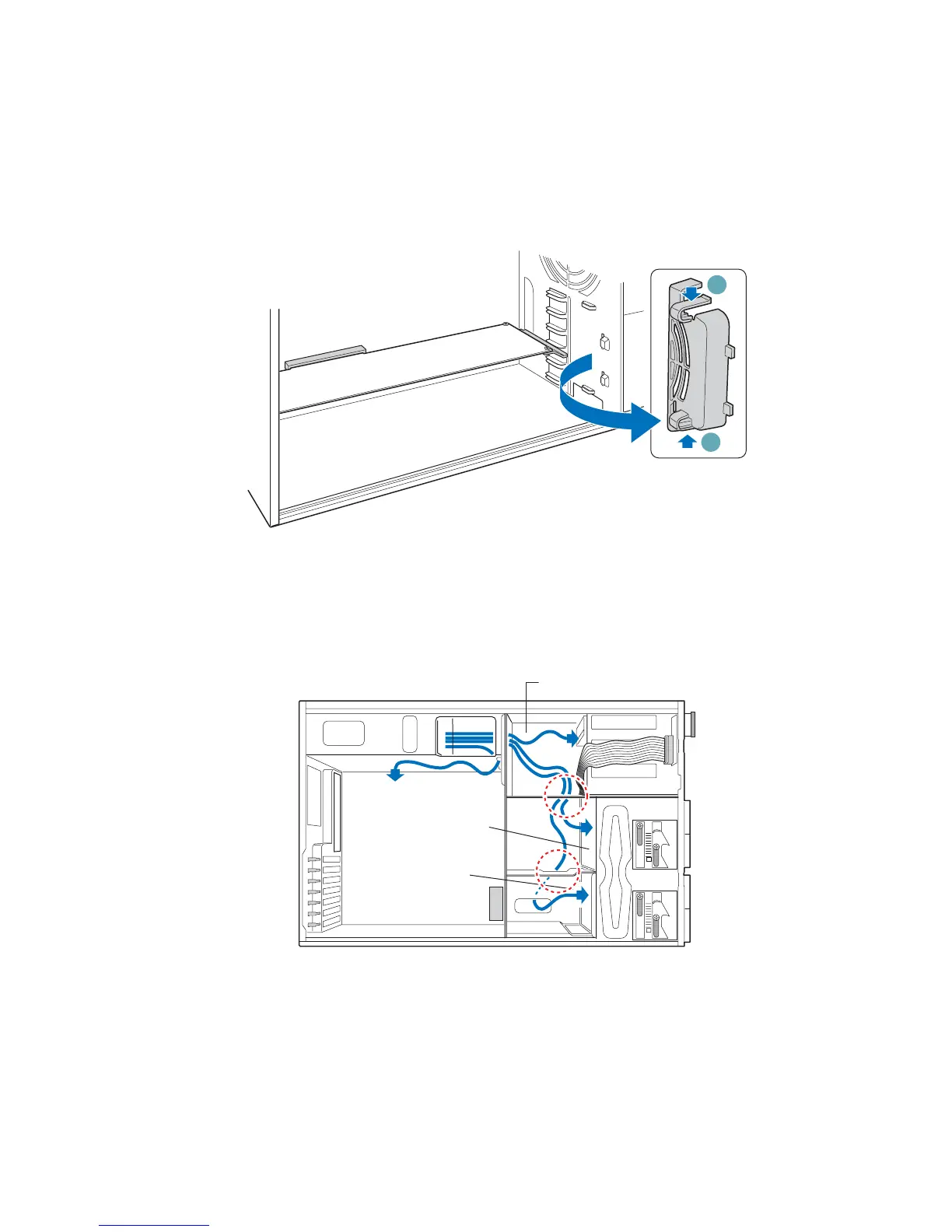
Route Power and Data Cables to the Fixed Drives
1. Press on two plastic tabs (letter “A”) and remove PCI Add-in Card Retainer (this will allow
access to the cable routing slot).
A
A
PCI Add-in
Card Retainer
TP00525
Figure 12. Removing PCI Add-in Card Retainer
2. Route the P1, P2, and P14 cables to the server board. Route the longest power cables (P8, P9,
P10, and P11) to the six-drive bay. Route the shorter cables (P3, P4, and P5) to the upper device
bay. Route the P6 and P7 power cables to the four-drive bay. Route the SATA drive power
cables to whichever drive bay is using SATA fixed drives.
TP00528
To Upper Device Bay
To Server
Board
To 4-Drive
Cage
To 6-Drive
Cage
Figure 13. Routing Power Cables to Fixed Drives