Intel® Server Board SE7520BD2 Technical Product Specification Error Reporting and Handling
Revision 1.3 Intel Confidential
131
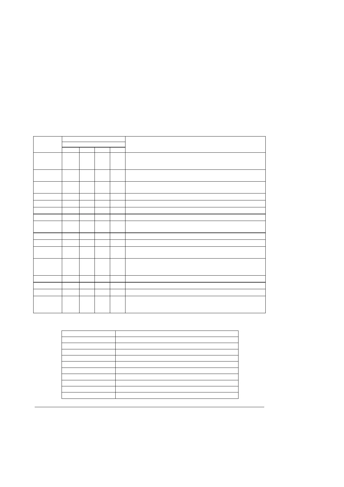
5.4.6 Boot Block Recovery Code Checkpoint
The boot block recovery code gets control when the BIOS determines that a BIOS recovery
needs to occur because the user has forced the update or the BIOS checksum is corrupt. The
following table describes the type of checkpoints that may occur during the boot block recovery
portion of the BIOS.
Table 69. Boot Block Recovery Code Checkpoint
Diagnostic LED Decoder
G=Green, R=Red, A=Amber
Checkpoint
MSB LSB
Description
E0 R R R OFF
Initialize the floppy controller in the super I/O. Some interrupt vectors
are initialized. DMA controller is initialized. 8259 interrupt controller is
initialized. L1 cache is enabled.
E9 A R R G
Set up floppy controller and data. Attempt to read from floppy.
Determine information about root directory of recovery media.
EA A R A OFF
Enable ATAPI hardware. Attempt to read from ARMD and ATAPI CD-
ROM. Determine information about root directory of recovery media.
EB A R A G Disable ATAPI hardware. Jump back to checkpoint E9.
EF A A A G Read error occurred on media. Jump back to checkpoint EB.
F0 R R R R Search for pre-defined recovery file name in root directory.
F1 R R R A Recovery file not found.
F2 R R A R
Start reading FAT table and analyze FAT to find the clusters occupied
by the recovery file.
F3 R R A A Start reading the recovery file cluster by cluster.
F5 R A R A Disable L1 cache.
FA A R A R
Check the validity of the recovery file configuration to the current
configuration of the flash part.
FB A R A A
Make flash write enabled through chipset and OEM specific method.
Detect proper flash part. Verify that the found flash part size equals
the recovery file size.
F4 R A R R The recovery file size does not equal the found flash part size.
FC A A R R Erase the flash part.
FD A A R A Program the flash part.
FF A A A A
The flash has been updated successfully. Make flash write disabled.
Disable ATAPI hardware. Restore CPUID value back into register.
Give control to F000 ROM at F000:FFF0h.
Table 70. Boot Block Recovery Beep Code
Beep Code Description
1 Insert diskette in drive A:
2 ’AMIBOOT.ROM’ file not found in root directory
3 Change Floppy Disk
4 Flash program successful
5 Floppy read error
7 No flash present
8 Floppy controller error
10 Flash erase error
11 Flash program error
12 Wrong bios file size