Platform Management ArchitectureIntel® Server Board SE7520BD2 Technical Product Specification
70 Revision 1.3
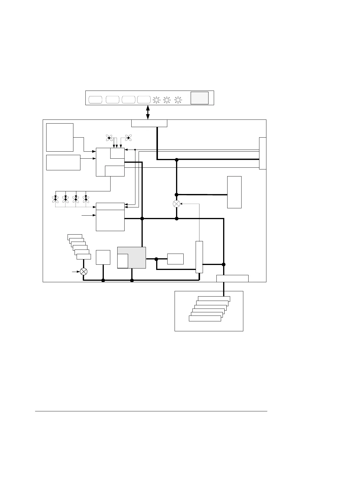
BASEBOARD
ID Reset
FRONT PANEL
Temp
Sensor
Power
IDFault
Power
NMI
Power Connector
PROC 1 & 2
- Therm Trip
- IERR
- Proc Hot
- Temperature
- VIDs
- VRM Voltage
Drive Backplane
Connector
IPMB Connector
Front Panel Connector
Heceta 7
Baseboard Voltages
VRD Temperatures
SCSI Term. Voltage
Fan PWM
Out 1&2
Fan
Tach In
CPU 1&2
1U PCI
SIO 3
Fan Tach In
BB Fans
Chas. Intr.
Anvik
NIC
ICH
SMBus
I
2
C 1
FMM Connector
Mini BMC
SDR
FRU
SEL
I
2
C 2
DIMM6
DIMM5
DIMM4
DIMM3
DIMM2
DIMM1
PWR_GOOD
Power Control
Power Control FRU
PS1
PS1 FRU
PS2
PS2 FRU
FMM Present
IPMB
POWER UNIT
Figure 10. Block Diagram of Platform Managment Architecture
4.1.2 5V Standby
The power supply must provide a 5V Standby power source for the platform to provide any
management functionality. 5V Standby is a low power 5V supply that is active whenever the
system is plugged into AC power. 5V Standby is used by the following onboard management
devices:
• Management Controller (BMC and/or mBMC) and associated RAM, Flash, and
SEEPROM which are used to monitor the various system power control sources