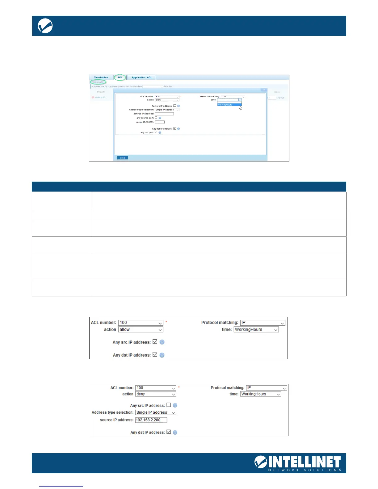
SET UP ACL
In this section, set up the actual Access Control List (ACL). The ACL connects IP address and port information
with a timetable (see previous section) and an action to either allow or deny access to the network through
the switch. The example below creates an ACL, which allows access to the network for any computer
Item Description
ACL Number Each ACL rule gets a number. Select the one from the drop-down list for which you
want to create this ACE (Access Control Entry).
Action Dene whether this rule grants access (“allow”) to the network, or prohibits it (“deny”).
SRC/DEST IP
Address
Specify the source and destination IP address for this ACE. You can provide a single IP
address (e.g., 192.168.2.100) or a specic network (e.g., 255.255.255.0).
SRC/DEST Port This option is only visible if the ACE is created for TCP or UDP. It will not show for IP
ACLs (see next parameter). You can provide a single port or a range of ports.
Protocol Matching IP: The ACE is applied to packets based on their source and/or destination IP address.
TCP/UDP: The ACE is applied to packets based on their source and/or destination IP
address and the port number for the selected protocol.
Time If you want to limit the ACE to a specic timetable (see section ab), you can select it
from the drop-down list.
Example 1 – Disallow access to the network for any computer outside of the working hours.
Example 2 – Disallow access to the network for an individual IP address during the working hours.