Power
• Input: 90 – 240 V AC, 50 – 60 Hz
• Power consumption: 431.7 watts (maximum)
Environmental
• Metal housing
• Dimensions: 330 (L) x 440 (W) x 44 (H) [mm] / 12.99 (L) x 17.32 (W) x 1.73 (H) [in]
• Weight: 4.7 kg (10.4 lbs.)
• Operating temperature: 0 – 45°C (32 – 113°F)
• Operating humidity: 10 – 90% RH, non-condensing
• Storage temperature: -40 – 70°C (-40 – 158°F)
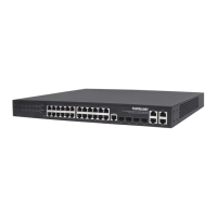
EXTERNAL COMPONENT DESCRIPTION
FRONT PANEL
The front panel of the switch consists of 24 10/100/1000 Mbps RJ-45 ports, four SFP ports, one Console port,
one Reset button and a series of LED indicators as shown below.
10/100/1000 Mbps RJ-45 ports (1 – 24):
Designed to connect to the device with a bandwidth of 10 Mbps, 100 Mbps or 1000 Mbps. Each has a
corresponding 10/100/1000 Mbps LED.
Combo ports (25 – 28S, 25 – 28T):
For the installation of up to four SFP modules; oers four SFP receiver slots, which are shared with four
related RJ45 ports (25 – 28T).
Console port (Console):
Designed to connect with the serial port of a computer or terminal for monitoring and conguring
the switch.
Reset button (Reset):
To restore the system factory default settings, press the reset button for ve seconds while the device is
powered on.
LED indicators:
The LED indicators will allow you to monitor, diagnose and troubleshoot any potential problem with the
switch, its connection or attached devices.
The following chart shows the LED indicators of the switch along with explanation of each indicator.
LED COLOR STATUS STATUS DESCRIPTION
Power Red
On Power On
O Power O
LINK/ACT/
Speed
(1 – 24)
10/100 Mbps:
Amber
On A device is connected to the port
O
No device is connected to the port
1000 Mbps:
Green
Flashing
Sending or receiving data
SFP
(25S – 28S)
Green
On A device is connected to the port
O No device is connected to the port
Flashing Sending or receiving data