D-0126440-A – 2020/08
VisualEyes™ 515/525 Instructions for Use - US Page 24
The patient must be prepared with the electrodes based on the chosen montage type. The operator can verify
the electrode placement against the labels on the pictures shown in the software. The default montage can
be set from Configuration > System Default Settings > ENG. The patient’s skin has to be abraded with
alcohol-free pumice pads and dried before placing the electrodes. Before starting the test, It is important to do
the impedance test (refer to section 2.1 of additional information guide) to verify proper electrode signal
reception. Once the operator gets the acceptable level of impedance (refer to section 2.1 of additional
information guide), she/he can proceed with the calibration (refer to section 4.6) for the individual test of a test
battery followed by the actual test.
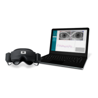
4.5.5 Placing the goggles on the patient
When a patient is decided to be tested using goggles, the goggles must be placed appropriately. Ensure that
the goggle cover is taken off while you place the goggle on the patient’s face. Adjust the strap for a snug fit.
For vision-denied testing, place the cover back on the goggles. Confirm with the patient that there is no light
leakage. If the patient still sees light, adjust the goggle’s position and tightness of the strap as needed.
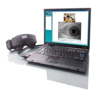
4.5.6 Eye image adjustment
After placing the goggle on every individual patient, if necessary, the operator adjusts the eye image in order
to track the patient’s pupils adequately. Tap the ‘BEGIN TESTING’ button from the main screen, which will
open the first test and display the eye images on the test screen. Center the eyes so that they appear in the
middle of the image window (refer to Figure 4.5-6). If using the side mounted camera goggles, use the
alignment knobs on the sides of the cameras (top knob for vertical adjustment, front knob for horizontal
adjustment). If using the top mounted camera goggles, use the center eyes button found in the tools between
the eye images or remote to adjust the eye image. If using the front mounted camera goggles, use both the
center eyes button and manual adjustment of the camera in the goggle viewport to center and align the eye
image. Use the focus knobs on the front and top mounted goggles to bring the eye image(s) into focus. The
infrared reflections will be the smallest when the cameras are in optimal focus.
Figure 4.5-6 Center eyes button
4.6 Calibration
It is important to do the standard calibration on every individual patient before starting any test in the
VisualEyes™ system. In general, 5-point calibration is performed as the standard calibration method.
Note: If a rotational chair is used for the test, the operator has to ensure that the chair is faced towards the
television screen/projection image, that the patient is centered in front of the stimulus and that the chair is
locked to avoid unintended turns before starting the calibration.
From the left menu panel of the test, tap ‘Calibration’ to open the calibration screen. The calibration target
will be displayed on the TV, projector screen or booth wall. The calibration target and calibration source
hardware can be changed from the selection boxes when switching between tests with different hardware
(e.g. EyeSeeCam goggle for EyeSeeCam vHIT). Use the ‘Target Center position’ slider to adjust the target’s
center position on the TV or projector to the patient’s eye level. The target center in the booth enclosure can
be manually adjusted by adjusting the laser box. Tap Start Calibration and instruct the patient to follow the
target as it moves to the five calibration points. If the calibration is useable, the circles will be filled with green
checkmarks. If the calibration is not optimal, the circles will be filled with red x marks. Calibration should be
repeated if green check marks are not obtained for all five calibration points.