32 ZeroWire Installation Manual
Connecting Outputs
ZeroWire has two general purpose outputs located on the rear of the unit. These can be
connected to up to 2 devices. Use the supplied header cable.
Outputs are controlled by Actions in the ZeroWire.
When an output is configured with an action, the output will monitor the status of the
action:
• When the action logic is true, the output will be on
• When the action is false
, the output will be off
If no action is assigned to an output the default behavior is:
• Output 1 = Siren
• Output 2 = Strobe
To program outputs from ZeroWire Web Server:
1. Click Advanced – Actions
2. Create an Action – refer to ZeroWire Reference Guide for more help
3. Click Advanced – Devices – System Devices – Control
4. Click “Control Output 1” or “Control Output 2”
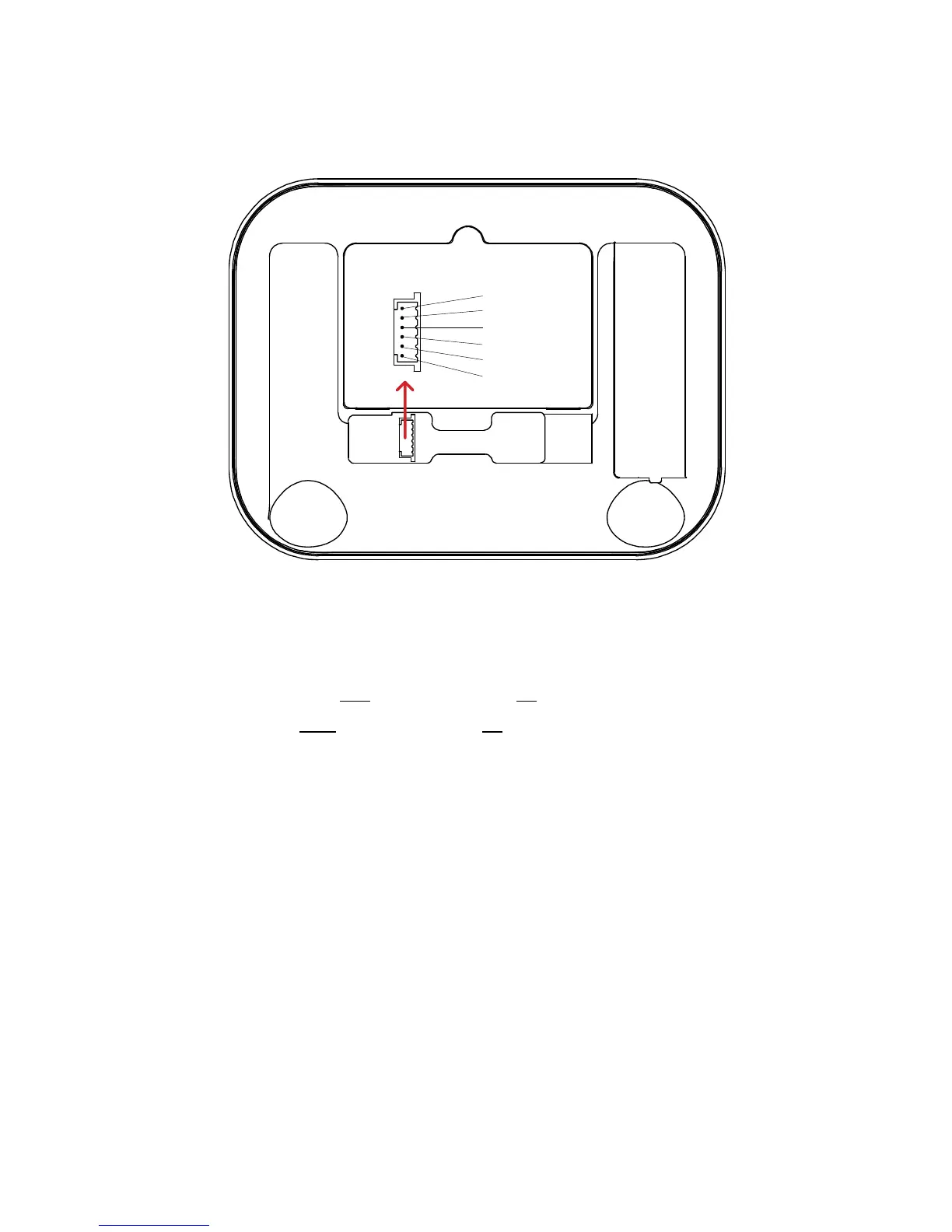
Input/Output
Connector
1. Ground
2. Input 1
3. Input 2
4. Output 1
5. Output 2
6. 8.5V+
Pin Outs