EasyManuals Logo

Invertek Drives Eco Optidrive Series User Manual

Invertek Drives Eco Optidrive Series
52 pages
To Next Page IconTo Next Page
To Previous Page IconTo Previous Page
Page #44 background imageLoading...
Page #44 background image
Optidrive Eco User Guide Revision 2.01
44
www.microlectra.nl
Serial communications
11
11.3.4. BACNet MSTP commissioning
In order to connect the drive and operate on a BACNet MSTP network, the following procedure should be used.
1. Set P1-14 = 101 to allow access to the extended parameters
2. On each drive, set a unique MAC ID in parameter P5-01
3. Set the required MSTP baudrate in P5-03
4. Select the required data format in P5-04
5. Define a unique BACNet Device Instance ID for each drive using parameters P5-09 and P5-10
6. Select control from BACNet connection by setting P1-12 = 6
11.3.5. Object Dictionary
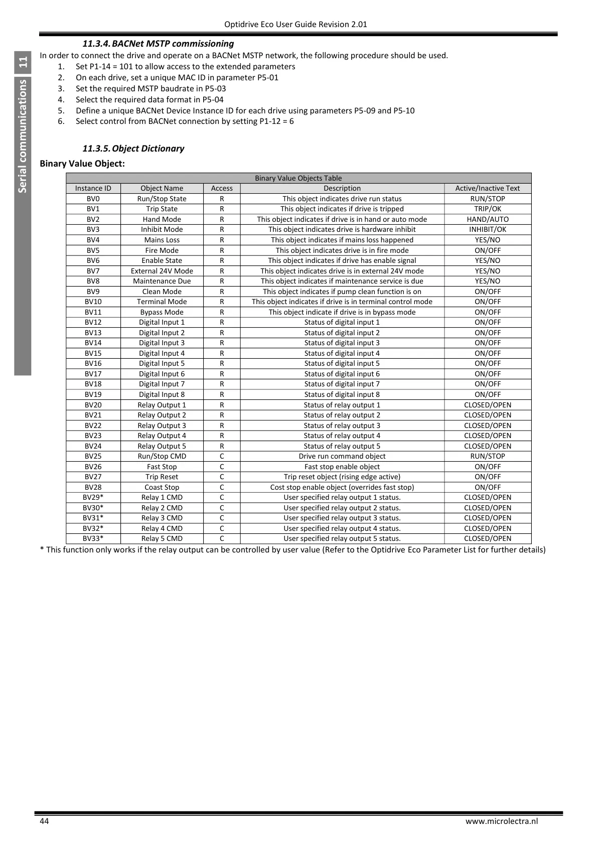
Binary Value Object:
Binary Value Objects Table
Instance ID
Object Name
Access
Description
Active/Inactive Text
BV0
Run/Stop State
R
This object indicates drive run status
RUN/STOP
BV1
Trip State
R
This object indicates if drive is tripped
TRIP/OK
BV2
Hand Mode
R
This object indicates if drive is in hand or auto mode
HAND/AUTO
BV3
Inhibit Mode
R
This object indicates drive is hardware inhibit
INHIBIT/OK
BV4
Mains Loss
R
This object indicates if mains loss happened
YES/NO
BV5
Fire Mode
R
This object indicates drive is in fire mode
ON/OFF
BV6
Enable State
R
This object indicates if drive has enable signal
YES/NO
BV7
External 24V Mode
R
This object indicates drive is in external 24V mode
YES/NO
BV8
Maintenance Due
R
This object indicates if maintenance service is due
YES/NO
BV9
Clean Mode
R
This object indicates if pump clean function is on
ON/OFF
BV10
Terminal Mode
R
This object indicates if drive is in terminal control mode
ON/OFF
BV11
Bypass Mode
R
This object indicate if drive is in bypass mode
ON/OFF
BV12
Digital Input 1
R
Status of digital input 1
ON/OFF
BV13
Digital Input 2
R
Status of digital input 2
ON/OFF
BV14
Digital Input 3
R
Status of digital input 3
ON/OFF
BV15
Digital Input 4
R
Status of digital input 4
ON/OFF
BV16
Digital Input 5
R
Status of digital input 5
ON/OFF
BV17
Digital Input 6
R
Status of digital input 6
ON/OFF
BV18
Digital Input 7
R
Status of digital input 7
ON/OFF
BV19
Digital Input 8
R
Status of digital input 8
ON/OFF
BV20
Relay Output 1
R
Status of relay output 1
CLOSED/OPEN
BV21
Relay Output 2
R
Status of relay output 2
CLOSED/OPEN
BV22
Relay Output 3
R
Status of relay output 3
CLOSED/OPEN
BV23
Relay Output 4
R
Status of relay output 4
CLOSED/OPEN
BV24
Relay Output 5
R
Status of relay output 5
CLOSED/OPEN
BV25
Run/Stop CMD
C
Drive run command object
RUN/STOP
BV26
Fast Stop
C
Fast stop enable object
ON/OFF
BV27
Trip Reset
C
Trip reset object (rising edge active)
ON/OFF
BV28
Coast Stop
C
Cost stop enable object (overrides fast stop)
ON/OFF
BV29*
Relay 1 CMD
C
User specified relay output 1 status.
CLOSED/OPEN
BV30*
Relay 2 CMD
C
User specified relay output 2 status.
CLOSED/OPEN
BV31*
Relay 3 CMD
C
User specified relay output 3 status.
CLOSED/OPEN
BV32*
Relay 4 CMD
C
User specified relay output 4 status.
CLOSED/OPEN
BV33*
Relay 5 CMD
C
User specified relay output 5 status.
CLOSED/OPEN
* This function only works if the relay output can be controlled by user value (Refer to the Optidrive Eco Parameter List for further details)

Table of Contents

Questions and Answers:

Question and Answer IconNeed help?

Do you have a question about the Invertek Drives Eco Optidrive Series and is the answer not in the manual?

Invertek Drives Eco Optidrive Series Specifications

General IconGeneral
BrandInvertek Drives
ModelEco Optidrive Series
CategoryDC Drives
LanguageEnglish

Related product manuals