DA180 series basic AC servo drive Operating and running
-59-
5.1.4 Running in speed control mode
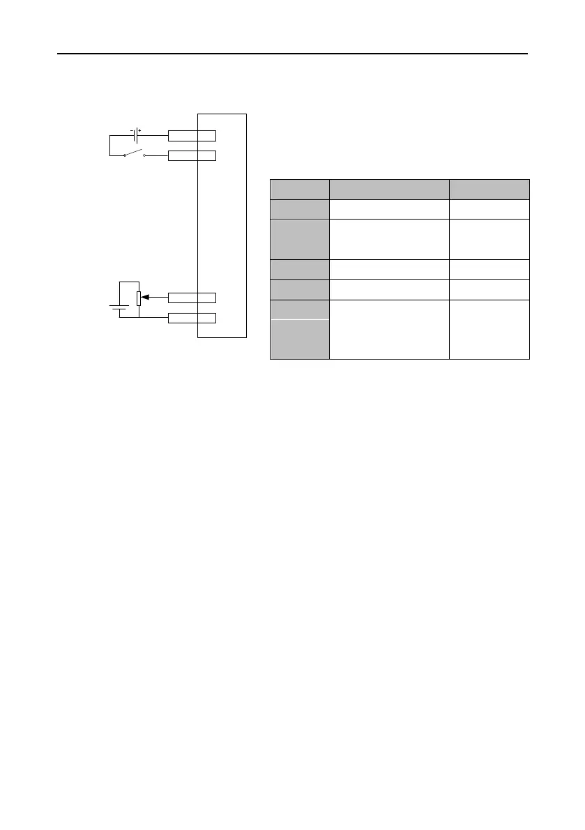
Simplified wiring
DC
12~24V
Servo drive
CN1
+
-
Upper analog
input 1
indicating
speed
command
0±10V
SON 16
COM+ 2
AD1 20
GND 6
Procedure
1. Complete the connect between the servo drive and servo motor.
2. Set P0.03 to 1, which indicates the speed control mode.
3. Switch off and re-switch on the main power for the setting of P0.03 to take effect.
4. Set P0.40 to 1, which indicates that the speed command source is external analog.
5. Set P3.26 to 3, which indicates that analog input 1 is a speed command.
6. Set P0.42 as required. See the description for P0.42 for details.
7. Connect the plug terminals for CN1.
8. Connect the plug of CN1 to the drive, switch on the power, and ensure that SON and 24V GND
are connected. The servo enters the locking state.
9. The motor shaft may rotate at a low speed if there is no upper command voltage. It is necessary
to adjust P3.20. See the description for P3.20 for details.
Depends on
the actual
situation.
 Loading...
