EasyManua.ls Logo

INVT DA180-S2R8SG0

INVT DA180-S2R8SG0
316 pages
To Next Page IconTo Next Page
To Previous Page IconTo Previous Page
Loading...
DA180 series basic AC servo drive Function codes
-224-
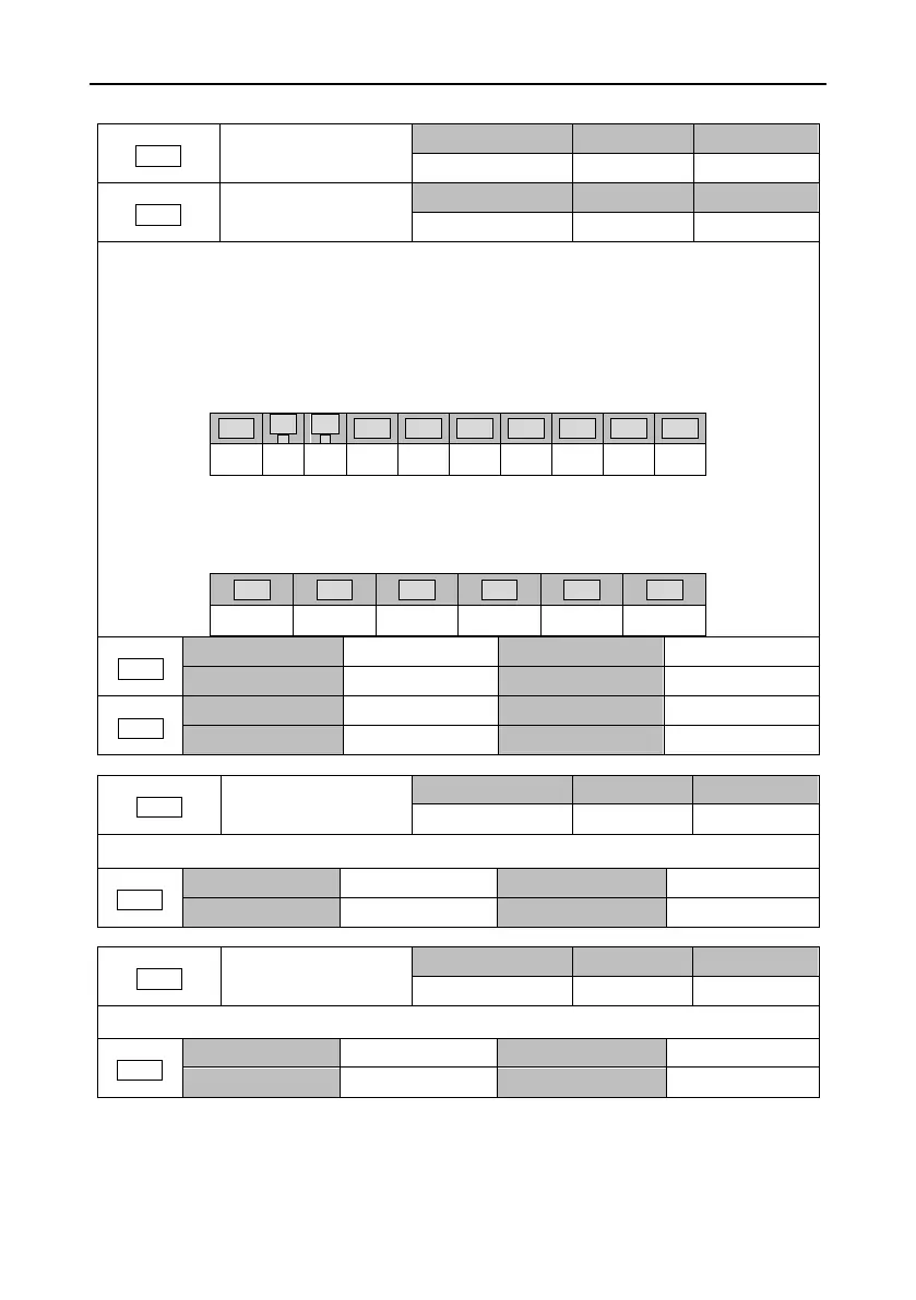
6.9.2 I/O monitoring (group R1)
R1.00
Digital input status
Setting range
Accuracy
Unit
0x0000x3FF
-
-
R1.01
Digital output status
Setting range
Accuracy
Unit
0x000x3F
-
-
Each of the parameters is a hexadecimal number, indicating the status of all digital terminals in
sequence. The terminal status ON is expressed by 1, while the terminal status OFF is expressed
by 0. Then the decimal number is converted to a hexadecimal number.
The digital input status is expressed by a three-bit hexadecimal number. The sorting order of digital
input is as follows:
(The bits not listed are padded with 0.)
BIT9
BIT
8
BIT
7
BIT6
BIT5
BIT4
BIT3
BIT2
BIT1
BIT0
SI10
SI9
SI8
SI7
SI6
SI5
SI4
SI3
SI2
SI1
The digital output status is expressed by a two-bit hexadecimal number. The sorting order of digital
output is as follows:
(The bits not listed are padded with 0.)
BIT5
BIT4
BIT3
BIT2
BIT1
BIT0
SO6
SO5
SO4
SO3
SO2
SO1
R1.00
Data size
16bit
Data format
HEX
Modbus address
4200, 4201
CANopen address
0x3100, 0x00
R1.01
Data size
16bit
Data format
HEX
Modbus address
4202, 4203
CANopen address
0x3101, 0x00
R1.02
Raw voltage of AI 1
Setting range
Accuracy
Unit
-10.00010.000
0.001
V
This parameter displays the unprocessed voltage of the analog input channel 1.
R1.02
Data size
32bit
Data format
DEC
Modbus address
4204, 4205
CANopen address
0x3102, 0x00
R1.03
Raw voltage of AI 2
Setting range
Accuracy
Unit
-10.00010.000
0.001
V
This parameter displays the unprocessed voltage of the analog input channel 2.
R1.03
Data size
32bit
Data format
DEC
Modbus address
4206, 4207
CANopen address
0x3103, 0x00

Table of Contents

Related product manuals