EasyManua.ls Logo

INVT DA180-S4R5SG0

INVT DA180-S4R5SG0
316 pages
To Next Page IconTo Next Page
To Previous Page IconTo Previous Page
Loading...
DA180 series basic AC servo drive Function codes
-98-
P0.62
Gain of AI 2
Setting range
Defaul
t
Unit
Applicable
mode
02000
100
[P3.27 unit]/V
P
S
T
This parameter specifies the gain of analog input 2. The gain unit is associated with P3.27.
Note:
Analog input 2 indicates the signal input from the analog speed/speed limit terminals (AD2 and
GND, corresponding to pin 20 and pin 19) of the CN1 plug.
Application example:
1. The function of analog input 2 is torque command.
2. The voltage of analog input 2 corresponds to the conversion gain of the motor torque command.
3. This parameter is valid only when P0.60 is 1.
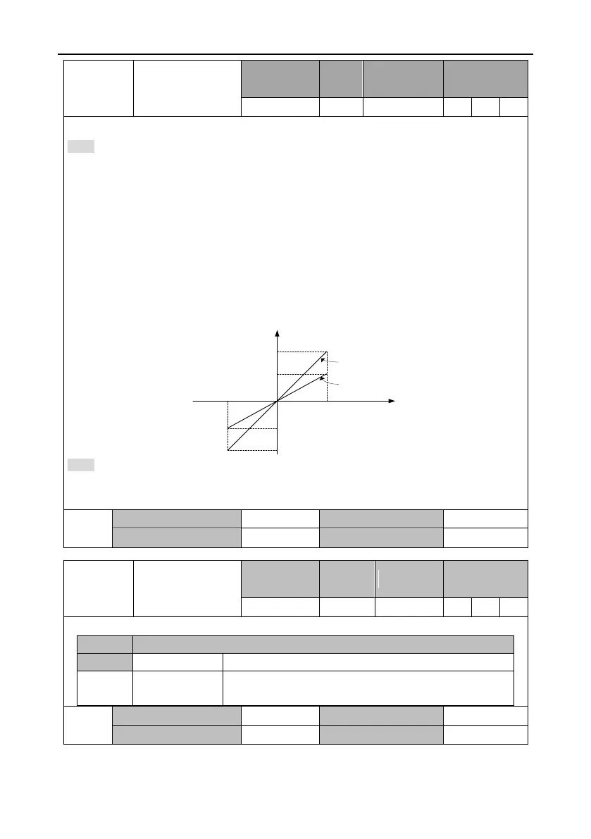
4. The relationship between the voltage of analog input 2 and torque command is as follows: The
torque corresponding to every 1V voltage is 10% of the rated torque by default.
Actual torque command = Analog input voltage x P0.62
-10.0V
100
-100
AD2 input voltage(V)
P
0.62=10%/V
P
0.62
=5%/V
50
-50
10.0V
Rated torque(%)
Note:
Set this parameter according to the motor working condition. If this parameter is set to a large
value, the motor speed may fluctuate sharply.
P0.62
Data size
32bit
Data format
DEC
Modbus address
1124, 1125
CANopen address
0x203E, 0x00
P0.63
Reverse of AI 2
Setting range
Default
Unit
Applicable
mode
01
0
-
P
S
T
This parameter specifies the voltage polarity of analog input 2.
Setting
Actual detection result
[0]
Positive polarity
[+Voltage] [Positive value], [-Voltage] [Negative value]
1
Negative
polarity
[+Voltage] [Negative value], [-Voltage][Positive value]
P0.63
Data size
16bit
Data format
DEC
Modbus address
1126, 1127
CANopen address
0x203F, 0x00

Table of Contents

Related product manuals