Electronic gear ratio concept: For any pulse input, the quantity and frequency of pulse actually
received by the drive can be changed by multiplying a certain coefficient. This coefficient is
electronic gear ratio. It can be divided into two parts: numerator and denominator:
Electronic gear ratio = g1/ g2
Of which,
g1: indicates the numerator of the electronic gear ratio
g2: indicates the denominator of the electronic gear ratio;
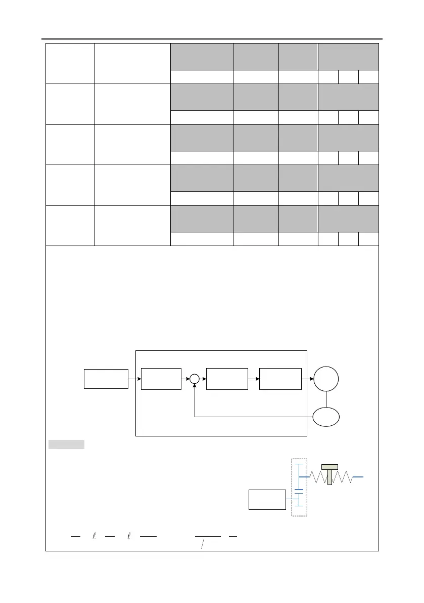
The following is the schematic diagram for the electronic gear ratio:
Example: The following is an example where 1 pulse is
equivalent to a feed rate of 10μm:
Mechanical specifications:
Feed of the ball screw Pb =10mm
DEC ratio n=3/5
Resolution of the servo motor encoder =10000
The electronic gear ratio is as follows:
 Loading...
