Goodrive300-19 series open loop vector inverter special for hosit Function parameters
-94-
Detailed instruction of parameters
Setting range of P08.33: -100.0~100.0% (FDT1
electrical level)
Setting range of P08.34: 0.00~P00.03 (the Max.
frequency)
Setting range of P08.35: -100.0~100.0% (FDT2
electrical level)
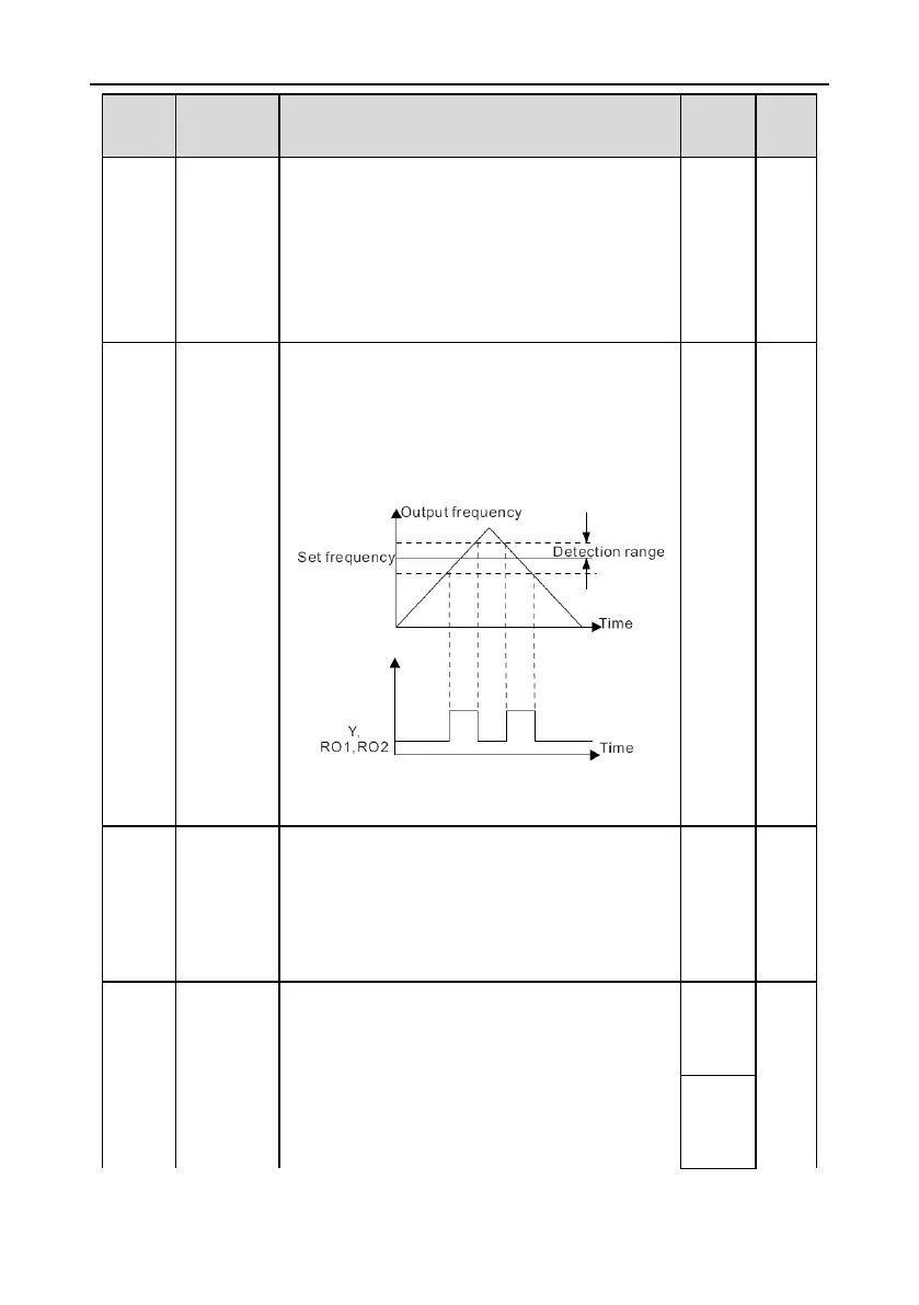
Frequency
arrival
detection
value
When the output frequency is among the positive or
negative detection range of the set frequency, the
multi-function digital output terminal will output the
signal of “frequency arrival”, see the diagram below
for detailed information:
The setting range: 0.00Hz~P00.03 (the Max.
frequency)
This parameter is used to control the internal braking
pipe inside the inverter.
0: Disable
1: Enable
Note: Only apply to internal braking pipe.
After setting the original bus voltage to brake the
energy, adjust the voltage appropriately to brake the
load. The factory changes with the voltage level.
The setting range: 200.0~2000.0V
In order to prevent customers set the value is too
large, it is recommended setting range:

 Loading...


