Goodrive35 Series Closed-loop Vector Control VFD Function parameters
98
Detailed instruction of parameters
(P00.03) or the max voltage (P04.31). Shorter the
integral time, stronger is the adjustment
Setting range: 0.00–50.00s
This parameter determines the strength of the
change ratio when PID adjustor carries out integral
adjustment on the deviation of PID feedback and
reference.
If the PID feedback changes 100% during the time,
the adjustment of integral adjustor (ignoring the
proportional effect and differential effect) is max.
output frequency (P00.03) or the max voltage
(P04.31). Longer the integral time, stronger is the
adjusting.
Setting range: 0.00–10.00s
This parameter means the sampling cycle of the
feedback. The adjustor operates each sampling
cycle. The longer the sapling cycle is, the slower the
response is.
Setting range: 0.001–1.000 s
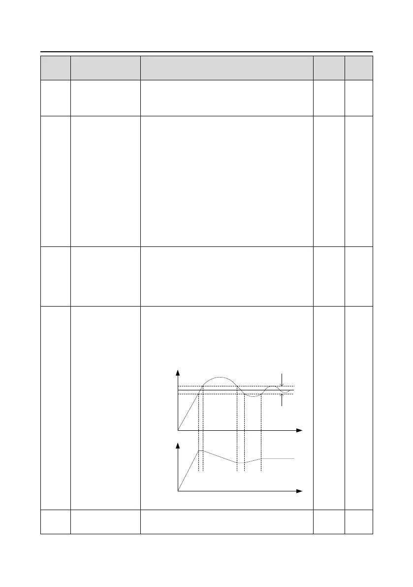
PID control deviation
limit
The output of PID system is the maximum deviation
relative to closed-loop reference. As shown in the
diagram below, PID adjustor stops to work during the
deviation limit. Set the function properly to adjust the
accuracy and stability of the system.
Reference
Deviation
limit
Feedback
Output
frequency f
Time t
Time t
Setting range: 0.0–100.0%
Output upper limit of
PID
This parameter is used to set the upper and lower
limit of the PID adjustor output.
 Loading...
