Goodrive35 Series Closed-loop Vector Control VFD Function parameters
72
Detailed instruction of parameters
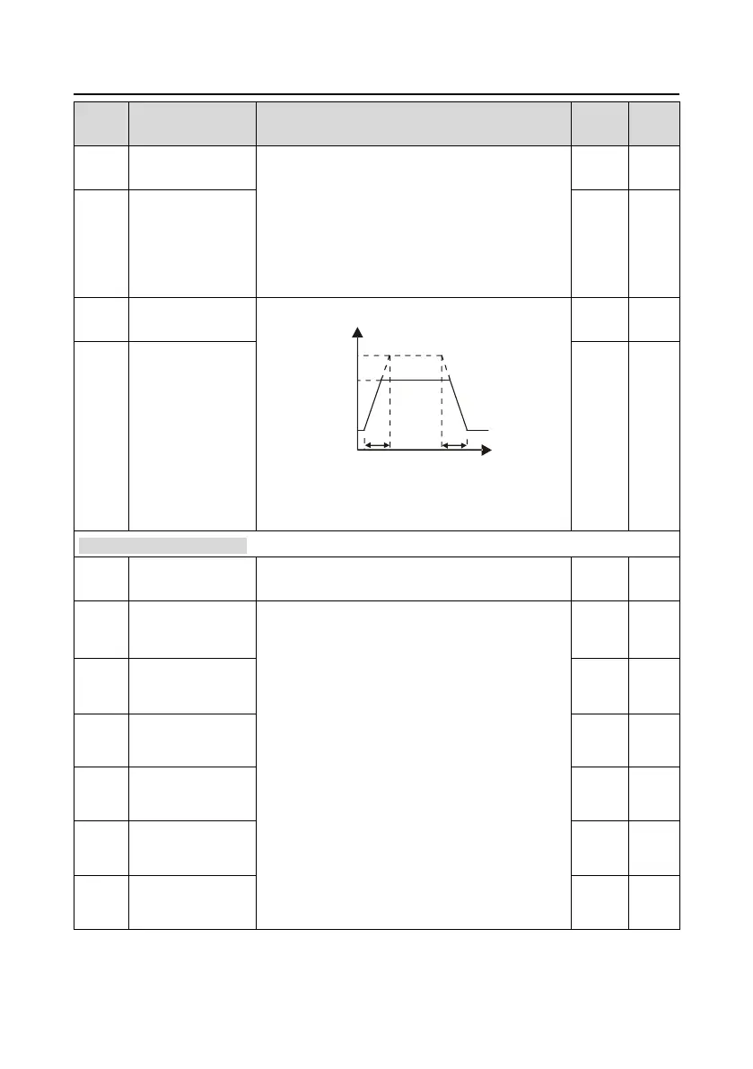
Voltage increasing time is the time when the VFD
accelerates from the output minimum voltage to the
output maximum voltage.
Voltage decreasing time is the time when the VFD
decelerates from the output maximum voltage to the
output minimum voltage.
The setting range: 0.0–3600.0s
Set the upper and low limit of the output voltage.
Vmax
Vmin
Vset
t1 t2
T
t1=P04.29
t2=P04.30
The setting range of P04.31: P04.32–100.0% (the
rated voltage of the motor)
The setting range of P04.32: 0.0%–P04.31
P05 Group Input terminals
0: High pulse input. See P05.49–P05.54
1: Digital input. See P05.09
0: No function
1: Forward rotation operation (FWD)
2: Reverse rotation operation (REV)
3: 3-wire control operation (SIn)
4: Forward jogging
5: Reverse jogging
6: Coast to stop
7: Fault reset
8: Operation pause
9: External fault input
10: Increasing frequency setting (UP)
11: Decreasing frequency setting (DOWN)
12: Frequency setting clear
13: Shift between A setting and B setting
14: Shift between combination setting and A setting

 Loading...