Goodrive35 Series Closed-loop Vector Control VFD Basic operation instruction
178
0
1
2
3
4
5
.
.
.
.
29
30
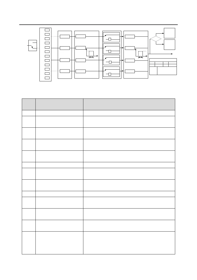
P06.01
P06.03
P06.04
P06.02
T delay
T delay
T delay
T delay
0
1
P06.05 output polarity
(default value is 0)
(default value is 0)
(default value is 0)
(default value is 0)
P06.00
HDO
Output type
0
1
0
1
0
1
Delay
0 Invalid 1 In running
3 In reverse running 4 In jogging
6
Frequency level detection
FDT1
7
Frequency level detection
FDT2
9 In zero speed running 10 Reach upper limit frequency
12 Ready to run 13 In pre-exciting
15 Underload prealarm 16 Simple PLC stage completed
2 In forward running
5 Inverter fault
8 Frequency reached
11 Reach lower limit frequency
14 Overload pre-alarm
17 Simple PLC cycle completed
18 Reach the set counting value ·19 Reach specified count value
21 Length reached 22 Reach running time
20 External fault reached
23
MODBUS communication
virtual terminal output
24
PROFIBUS communication
virtual terminal output
25~30 Reserved
0
1
-1
-1
-1
-1
P17.12
ON/OFF output
terminal
P07.38
present fault
ON/OFF output
terminal state
Fault?
Fault
Runnin
g
Y BIT0 HDO BIT1
ROI BIT2 RO2 BIT3
P06.05, P17.12, P07.38 display
P06.00
0: Open collector high
speed pulse output
1: Open collector output
P06.07
P06.09
P06.11
P06.13
Y
RO2
ROI
HDO
Digital switch-off delay time
Digital output
T delay
T delay
T delay
T delay
Delay
P06.06
P06.08
P06.10
P06.12
Digital switch-on delay time
The below table is the option of the four function parameters and selecting the repeated output
terminal function is allowed.
The output terminal has no function.
Output ON signal when the VFD is running and there is
frequency output.
Output ON signal when the VFD is running forward and
there is frequency output.
Output ON signal when the VFD is running reverse and
there is frequency output.
Output ON signal when the VFD is jogging and there is
frequency output.
Output ON signal when the VFD is in fault
Please refer to P08.32 and P08.33 for detailed
information.
Please refer to P08.34 and P08.35 for detailed
information.
Please refer to P08.36 for detailed information.
Output ON signal when the output frequency and given
frequency of the VFD is 0 at the same time.
Upper-limit frequency arrival
Output ON signal when the running frequency of the VFD
is the upper limit frequency.
Upper-limit frequency arrival
Output ON signal when the running frequency of the VFD
is the lower limit frequency.
When the main circuit and the control circuit are
established and the protection function of the VFD is not
active. The VFD is in the running state and it will output
ON signal.

 Loading...