Goodrive35 Series Closed-loop Vector Control VFD Communication protocol
217
It is recommended to use shield cables and make the shield layer as the grounding wires during
RS485 remote communication.
In the cases with less devices and shorter distance, it is recommended to use 120Ω terminal resistor
as the performance will be weakened if the distance increases even if the network can perform well
without load resistor.
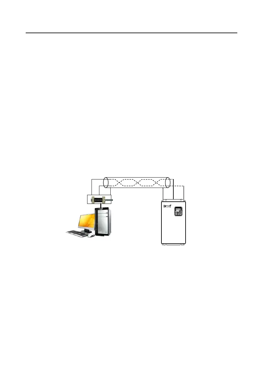
10.3.1.1 Single application
Figure 10-1 is the site Modbus connection figure of single VFD and PC. Generally, the computer does
not have RS485 interface, the RS232 or USB interface of the computer should be converted into
RS485 by converter. Connect the A terminal of RS485 to the 485+ terminal of the VFD and B to the
485- terminal. It is recommended to use the shield twisted pairs. When applying RS232-RS485
converter, if the RS232 interface of the computer is connected to the RS232 interface of the converter,
the wire length should be as short as possible within the length of 15m. It is recommended to connect
the RS232-RS485 converter to the computer directly. If using USB-RS485 converter, the wire should
be as short as possible, too.
Select a right interface to the upper monitor of the computer (select the interface of RS232-RS485
converter, such as COM1) after the wiring and set the basic parameters such as communication baud
rate and digital check bit to the same as the VFD.
VFD
Computer
Twisted pairs with shield screen
485+485-
Earth
B
A
Earth
B
A
RS485 route
Convert from RS232
to RS485
Figure 10-1 RS485 physical connection in single application
10.3.1.2 Multi-application
In the real multi-application, the chrysanthemum connection and star connection are commonly used.
Chrysanthemum chain connection is required in the RS485 industrial fieldbus standards. The two
ends are connected to terminal resistors of 120Ω which is shown as Figure 10-2. Figure 10-3 is the
simply connection figure and Figure 10-4 is the real application figure.

 Loading...