Goodrive35 Series Closed-loop Vector Control VFD Extension card
251
21: MSB of position reference (signed
digit)
22: LSB of position reference (unsigned
digit)
23: MSB of position feedback (signed digit)
24: LSB of position feedback (unsigned
digit)
25: State words
PKW area (parameter identification marks PKW1-value area). PKW area describes treatment of
parameter identification interface, PKW interface is a mechanism which determine parameters
transmission between two communication partners, such as reading and writing parameter values.
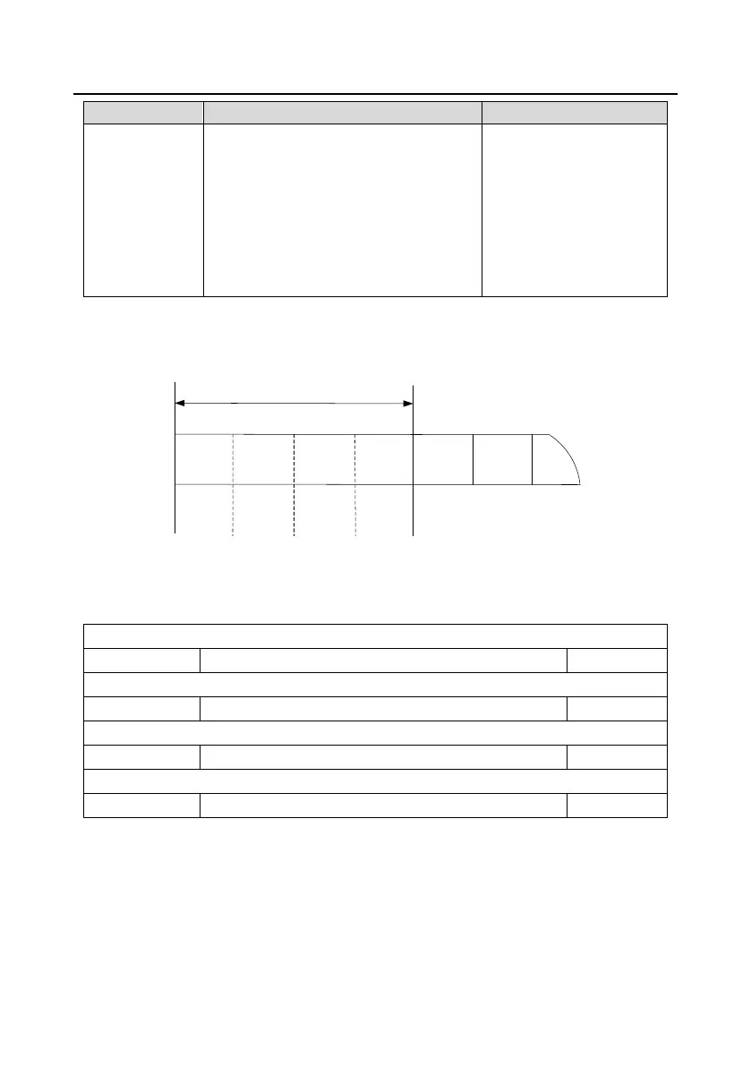
Structure of PKW zone (PWK)
Process data
Parameters
Parameter
address
Request
mark
Response
mark
Fault code
PKW1 PKW2
PKW3 PKW4
CW
SW
PZD2
PZD2
……
Parameter identification zone
In the process of periodic PROFIBUS-DP communication, PKW area is composed of four words (16
bit), each word is defined as follows:
The first word PKW1 (16 bit)
Task or response identification marks
The second word PKW2 (16 bit)
The third word PKW3 (16 bit)
Parameter value (high word) or return error code value
The fourth word PKW4 (16 bit)
Parameter value (low word)
Note: If the master requests one parameter value, the value of PKW3 and PKW4 will not be valid.
Task requests and responses: When passing data to slave machine, master machine use request
label while slave machine use response label to positive or negative confirmation. The following table
lists the request/response functional.
The definition of task logo PKW1 is as follows:
 Loading...
