110
Inxpect SRE 200 Series| Instruction manual v1.5 DEC 2023 |Inxpect SAF-IM-200S_5m_7_00047_en_v1.5|© 2021-2023 Inxpect SpA
11. Technical references
11.2.2 Voltage and current limits
for digital inputs
The digital inputs (input voltage 24 V DC) adhere to
the following voltage and current limits, in
accordance with standard IEC/EN 61131-2:2003.
Type 3
Voltage limits
0 from - 3 to 11 V
1 from 11 to 30 V
Current limits
0 15 mA
1 from 2 to 15 mA
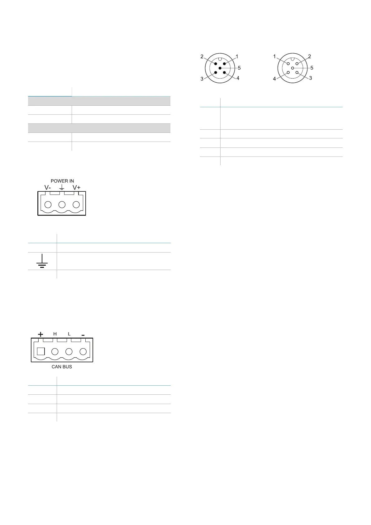
11.2.3 Power supply terminal
block
Note: connector front view.
Symbol Description
V- GND
Earth
V+ + 24 V DC
Note: the maximum operating temperature of the
cables must be at least 70 °C.
Note: use only copper wires with a minimum gauge
of 18 AWG and a torque of 0.62 Nm (5.5 lbs in).
11.2.4 CAN bus terminal block
Symbol Description
+ + 12 V DC output
H CAN H
L CANL
- GND
Note: the maximum operating temperature of the
cables must be at least 70 °C.
11.2.5 Connectors M12 CAN bus
Male connector Female connector
Pin Function
1 Shield to be connected to the functional
earth on the power supply terminal block
of the control unit.
2 +12 V dc
3 GND
4 CAN H
5 CANL


 To Next Page