28
Inxpect SRE 200 Series| Instruction manual v1.5 DEC 2023 |Inxpect SAF-IM-200S_5m_7_00047_en_v1.5|© 2021-2023 Inxpect SpA
3. Get to know Inxpect SRE 200 Series
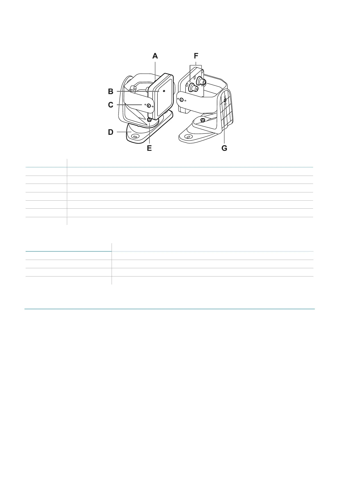
3.5.5 3-axes bracket
Part Description
A Sensor
B Status LED
C Tamper-proof screws to position the sensor at a specific angle around x-axis (tilt 10° steps)
D Mounting bracket
E Tamper-proof screw to position the sensor at a specific angle around y-axis (pan 10° steps)
F Connectors for connecting the sensors in a chain and to the control unit
G Tamper-proof screw to position the sensor at a specific angle around z-axis (roll 10° steps)
3.5.6 Status LED
Status Meaning
Steady blue Sensor is working. No motion detected.
Flashing blue Sensor is detecting motion. Not available if the sensor is in muting.
Purple Firmware update conditions (see "Sensor LED" on page87)
Red Error conditions (see "Sensor LED" on page87)
3.6 Inxpect Safety application
3.6.1 Functions
The application permits the following main functions to be performed:
l
Configure the system.
l
Create the configuration report.
l
Check system functioning.
l
Download system log.
3.6.2 Inxpect Safety application usage
To use the application, the control unit must be connected to a computer with a data USB cable or, if the Ethernet
port is available, an Ethernet cable. The USB cable allows to configure the system locally, whereas the Ethernet
cable allows to do it remotely.
The Ethernet communication between the control unit and the Inxpect Safety application is secured by the most
advanced security protocols (TLS).