Inxpect SRE 200 Series | Instruction manual v1.5 DEC 2023|Inxpect SAF-IM-200S_5m_7_00047_en_v1.5|© 2021-2023 Inxpect SpA
53
7. Sensor position
Contents
This section includes the following topics:
7.1 Basic concepts 53
7.2 Sensor field of view 53
7.3 Advanced field of view (5.x sensorsonly) 57
7.4 Dangerous area calculation 58
7.5 Calculation of range of distances 60
7.6 Sensor position recommendations 61
7.7 Installations on moving elements (Mobile application) 63
7.8 Outdoor installations 64
7.1 Basic concepts
7.1.1 Determining factors
The sensor installation height and inclination should be decided together with the angular coverage and the
detection distances in order to have optimal coverage of the dangerous area.
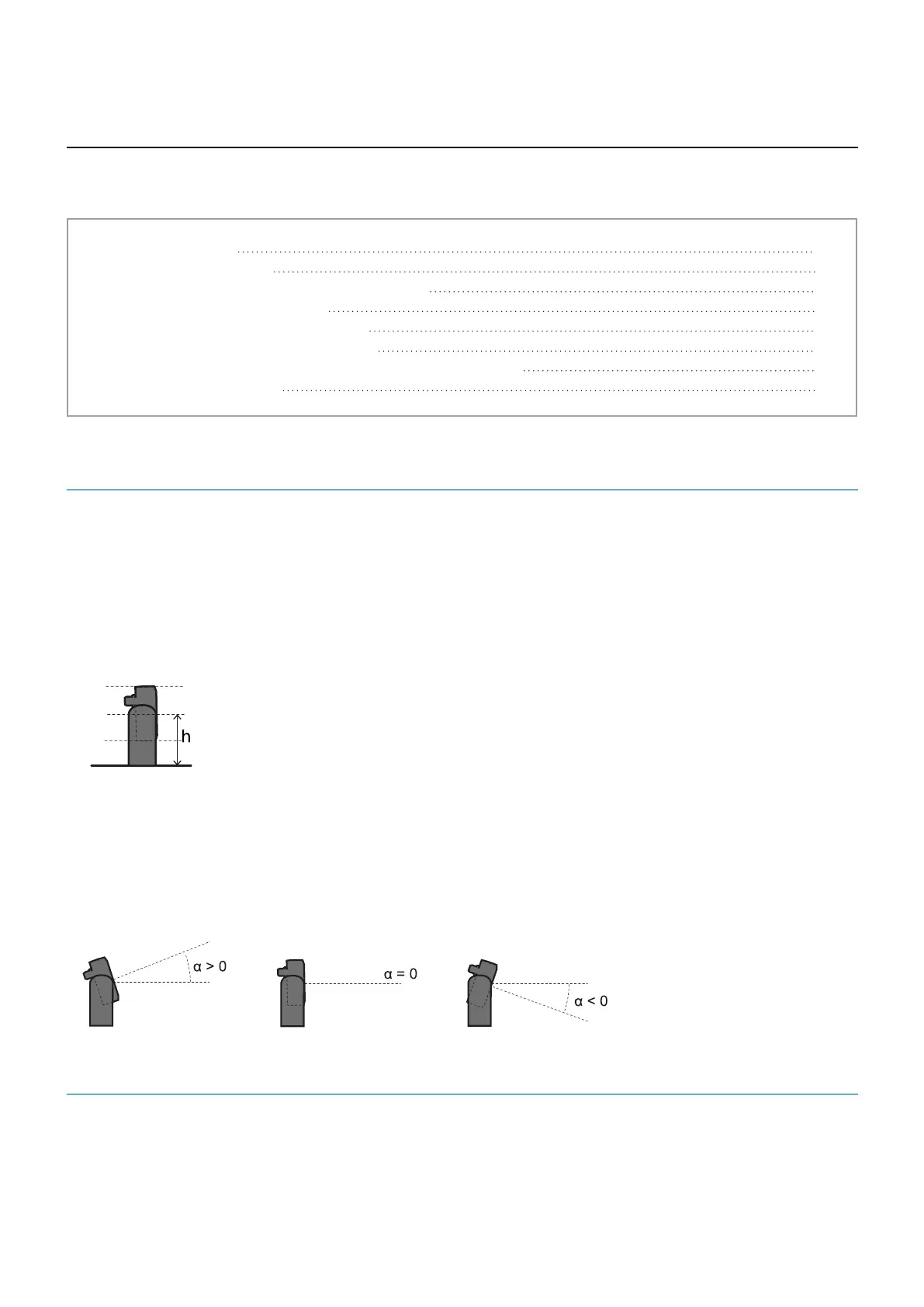
7.1.2 Sensor installation height
The installation height (h) is the distance between the center of the sensor and the ground or reference plane of
the sensor.
7.1.3 Sensor inclination
Sensor inclination is the rotation of the sensor around its x-axis. Inclination is defined as the angle between a line
perpendicular to the sensor and a line parallel to the ground. Three examples are presented as follows:
l
sensor tilted upwards: α positive
l
straight sensor: α = 0
l
sensor tilted downwards: α negative
7.2 Sensor field of view
7.2.1 Types of field of view
During the configuration phase, for each sensor it is possible to select the angular coverage (see "Angular
coverage" on page38).
The actual detection field of the sensor also depends on the sensor installation height and inclination (see
"Calculation of range of distances" on page60).


 To Next Page