6D3 – 18 CHARGING SYSTEM
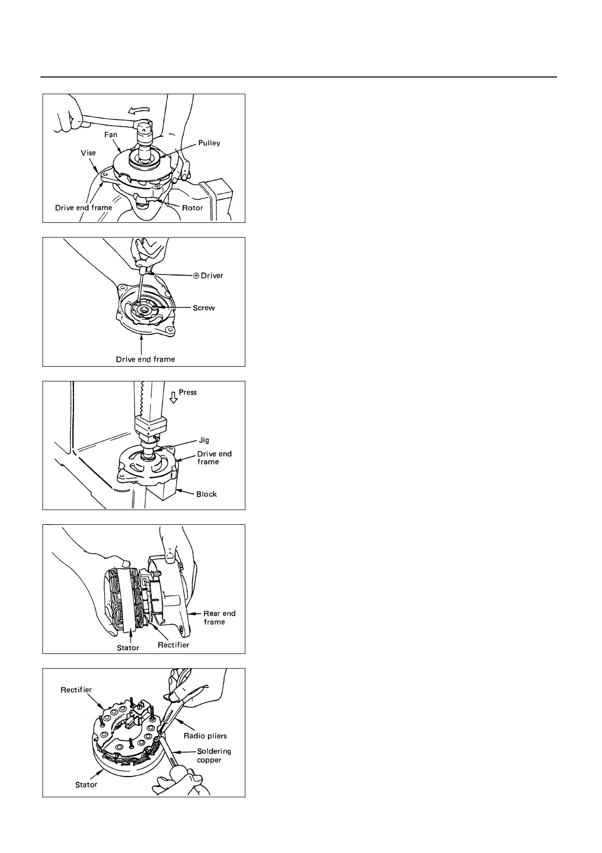
3. Separation of Pulley, Fan, Drive End Frame, and Rotor
Fix the rotor in a lock vice, and after removing the lock nut
separate the pulley, fan, drive end frame, and rotor.
NOTE:
Be sure to fix the rotor through cloth in a vice.
4. Removal of Bearing (on the Drive End Frame Side)
• Remove the ball bearing fixing screw.
• As shows in the illustration, make the drive end frame
parallel to a block, and then push out the bearing with
a press through a jig.
5. Separation of Rear End Frame and Rectifier & Stator
Remove the nuts M5 and M6, and separate the rectifier
and stator from the rear end frame.
6. Separation of Rectifier and Stator
Disconnect the stator lead wire from the rectifier by means
of a soldering copper to separate the rectifier and stator
from each other.
NOTE:
Since the rectifier a low resistance to heat, the work
should be done quickly using radio pliers to absorb
heat.
6D3-18-1.tif
6D3-18-2.tif
6D3-18-3.tif
6D3-18-4.tif
6D3-18-5.tif
 Loading...


