Installation
Copyright ©ITECH Electronic Co., Ltd. 31
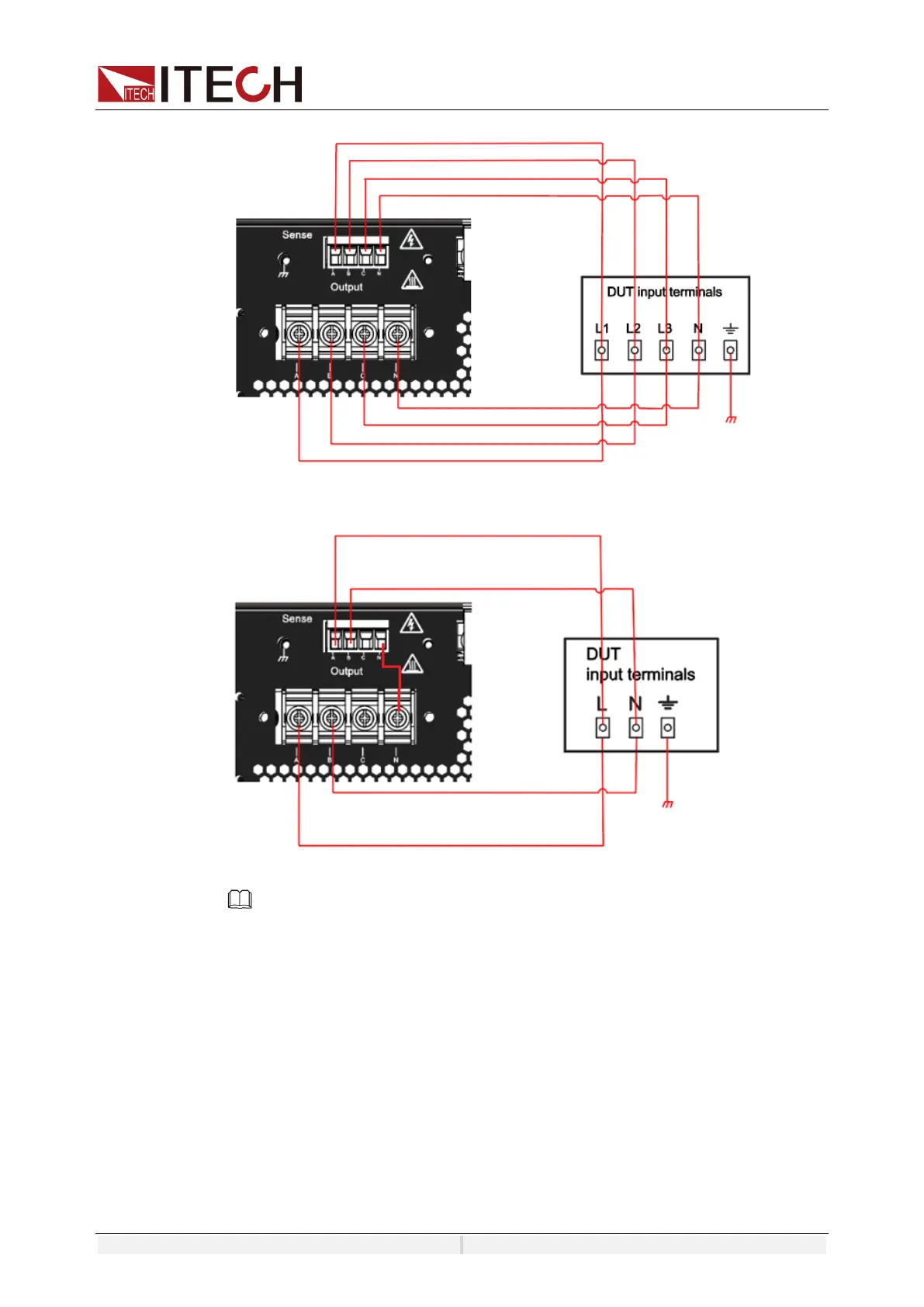
⚫ The connection diagram of three phase is shown as follow:
⚫ The connection diagram of reverse phase is shown as follow:
NOTE
When the output voltage has DC voltage, the output terminal A is positive, and N is
negative.
1. Confirm that the power switch is in the OFF position and verify that there is
no dangerous voltage on the connection terminals.
2. Remove the output terminals cover of the power system.
3. Refer to the wiring diagram and connect the Vs+ and Vs- with armored
twisted-pair cables. Loosen the screws of the output terminals and connect
the red and black test cables to the output terminals. Re-tighten the screws.
When maximum current that one test cable can withstand fails to meet the
rated current, use multiple pieces of red and black test cables. For example,
the maximum current is 1,200A, then 4 pieces of 360A red and black cables
are required.
4. Thread the red and black test cables through the output terminals cover of
 Loading...