Source Mode Operation
Copyright ©ITECH Electronic Co., Ltd. 67
【Sync-in】: Synchronous input function, which is used to output frequency
lock or phase lock with the external signal. At this time, the machine
synchronizes the frequency or phase information input from the IO-4 pin.
【 Sync-out 】 : Synchronous output function, the IT7900 produces
synchronous signal to the outside, which is AC zero crossing pulse signal
sent from the IO port.
5. Set the IO-5 function of the first power supply. Select I/O -> Digital IO-5: On-
off Status, set Reverse to Off, and set Function to OnOff-status.
6. Set the IO-1 function of the second power supply. Select I/O -> Digital IO-
1:Remote inhibit input, set Reverse to On, and set Function to Inhibit-Living.
NOTE
The IO-1 function of the second power supply must set according as
above. Otherwise, the polyphase will be error.
⚫ Frequency and phase lock configuration
set frequency and phase synchronization Settings for the second power
supply.
On the Source Settings menu, select External Lock-Frequency Control
->Status->Lock-Phase.
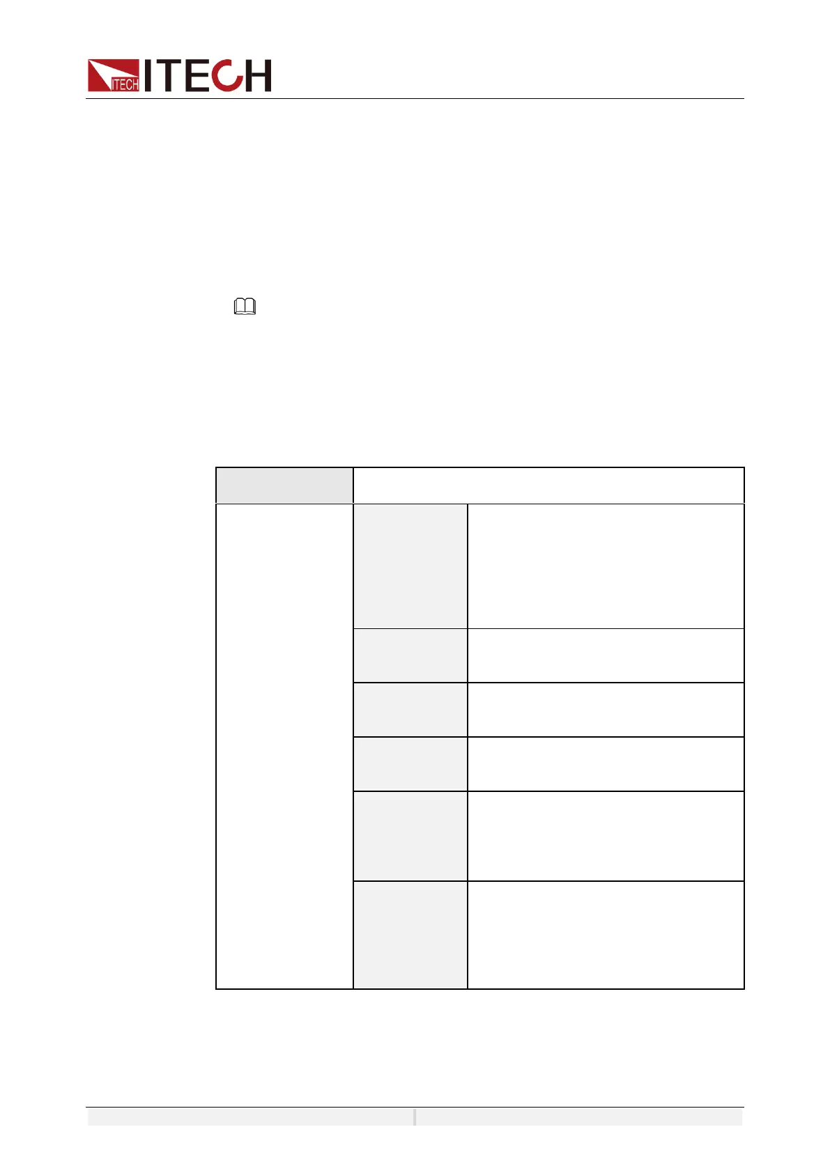
Set the frequency difference upper
limit between the output frequency
and the external I/O input signal.
Set the frequency difference upper
limit between the output frequency
and the external I/O input signal.
Set the output mode when the
frequency lock fails:
⚫ Output Disable: stop output
⚫ Limit: Output according to the set
frequency.
Synchronization mode selection
(settable only in fiber slave mode).
Local: The slave parameters take effect in
real time.
Fiber: The slave is controlled by the
master fiber.
If in balance mode, the Phase Delay between the first instrument and the
second intrument is set to 60° to achieve six-phase balanced output of 60°
between six phases.
 Loading...