8
ALS 4.0 XE
PRODUCT MANUAL
EN
1.2.3 Service Requirements
!
CAUTION
The use of a qualified electrician is required to ensure the
following service specifications are properly met.
Electrical
• Main Service
• 480VAC, 60A, 3PH, 60HZ (50 Hz Optional)
• Y-configuration preferred (delta acceptable)
• Phase Voltage Imbalance – 6 V
• e (Vt) – ≤ 50 Vsec @ ≤ 1 occurrence per half
hour
V
t
= V
i
× t
Where:
V
t
= Transient Voltage (Vsec)
V
i
= Instantaneous Voltage (V)
t = time (sec)
• Secondary Service
• 120 VAC, 20A, 1PH, 60 Hz (50Hz optional)
• This must be a dedicated line.
• Line conditioner recommended.
Air
• Place coalescer immediately prior to machine to
insure dry, oil-free air.
• Machine has a factory installed lter with pressure
regulator.
!
CAUTION
Introduction of oil to air system will damage seals.
NOTE
110 PSI is the minimum recommended pressure
in the main air line.
2. Getting to Know
the ALS 4.0
2.1 System Overview
Figure 1 (on page 7) indicates the names of the various
major components of the ALS 4.0 system.
NOTE
Standard infeed and small parts conveyor not shown in Figure 1.
2.2 Axes of Motion
Refer to Figure 2 (on page 9).
S Blade Motor
Spins the saw blade
(not shown, motor located inside enclosure)
L1P Printer Motor
Feeds lumber beneath the printer head and into
L1 (not shown)
L1 Infeed Feeds lumber and measures length
L2 Outfeed
Coordinates with L1 axis to feed lumber and
measure length
A Angle Sets the cut angle
B Bevel Sets the bevel angle (optional)
T Traverse Translates the saw blade across the lumber
Z Vertical Raises and lowers the blade
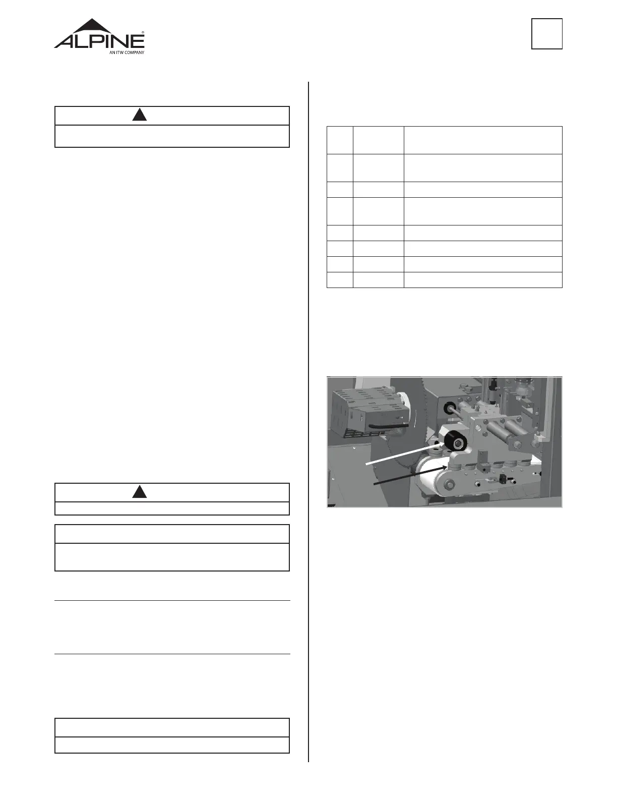
2.3 Infeed and Outfeed System
The Pushers and Clamps are sets of rollers attached to
the L1 and L2 drives. These rollers help maintain control
of the lumber as it moves through the saw to ensure
cuts are made accurately.
CLAMP
PUSHER
Figure 3
2.3.1 Clamp
The Clamp is a set of three black urethane-coated
rollers that “clamp” the lumber down onto the drive belt.
The picture on the right shows the L2 Clamp, located
directly above the drive belt. L1 contains an identical
Clamp.
2.3.2 Pusher
The Pusher is a set of small rollers that that “push” the
lumber against the back fence rollers as it is fed through
the saw. It is part of the L-drive assembly toward the
front of the saw, as shown in the picture of L2 on the
right. An identical Pusher can also be found on L1.
 Loading...