45
ALS 4.0 XE
PRODUCT MANUAL
EN
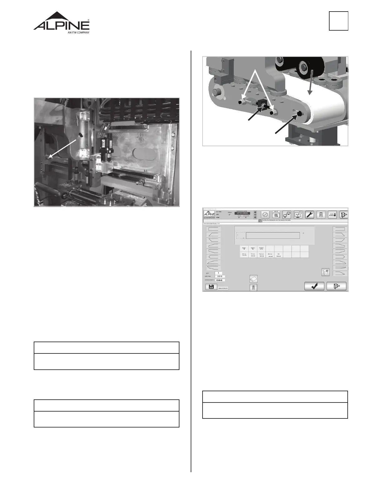
Lock nuts
Drive belt
Adjustment nut
Idler sprocket bolt
Figure 110
4.9 Calibrate Cut Length (L1/L2)
Step 1 – Check the L1/L2 belt tension (Section 4.8).
Step 2 – In SEMI AUTO mode, cut a board 15-11-0 and
measure and record the overall length as “Cut 1”.
Figure 111
Step 3 – Reduce the cut length by 0-1-0. Cut, measure
and record the overall length as “Cut 2”.
• If both cuts are accurate, the cut length is
calibrated. Go to the next section.
• If “Cut 1” and “Cut 2” are both long by the same
amount, or both short by the same amount
proceed to the next step.
• If the two cuts are o by dierent amounts,
contact Alpine Equipment Customer Service for
additional guidance.
NOTE
In some cases it may be necessary to repeat the cut 5-6 times to
determine the root cause of the inconsistent length.
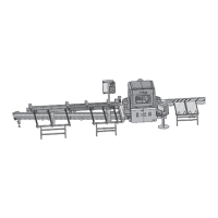
Step 22 – The Figure below shows the hard stop for
the T-axis. If the centerline of the cut is less than 1.75”,
extend the bolt. If the centerline of the cut is greater
than 1.75”, retract the hard stop bolt. Adjust the hard
stop the distance the centerline is o.
Figure 109
Step 23 – Remove the lockout/tagout.
Step 24 – Power the machine up and follow normal
startup and homing procedures (Section 3.1). Repeat
this section until calibration is complete.
4.8 L1/L2 Belt Tension Adjustment
In order to keep the ALS 4.0 running smoothly, it may be
necessary to adjust the belt tension from time-to-time.
Step 1 – Loosen the idler sprocket bolts on both the
front and back sides of the drive assembly, then loosen
the locknuts.
Step 2 – Using a 9/16” wrench, adjust the belt tension
assembly so that the belt can only be pulled away from
the rollers by 1/4”.
NOTE
Using an appropriate torque wrench, torque the adjustment nut
to 40 in-lbs.
Step 3 – Once the belt has been properly tensioned,
tighten the idler sprocket bolts on both sides of the
drive assembly and the two lock nuts.
NOTE
The tension of the L1 & L2 belts should be checked prior to
calibrating L1 & L2.
 Loading...