EN
ALS 4.0 XE
Product Manual
IMPORTANT! DO NOT DESTROY!
It is the customer’s responsibility to have employees read and understand this manual.
Read instructions completely before using the equipment.
The Latest
Evolution of the
I
ndustry’s Leading
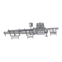
Linear Saw
The Alpine ALS 4.0 takes linear cutting to
the next level. The ALS 4.0 is designed for
production efficiency, only requiring one
sawyer for operation. The result is a reduction
in labor, a boost in production and an increase
to your bottom line.
This is not only an operation manual, but a
tool that can be utilized to gain the maximum
potential from your ALS 4.0 linear saw. Each
plant runs differently and the ALS 4.0 stands up
to the challenge—providing ultimate flexibility
in setup and operation.