P/N 960-000173R_Rev. A {EDP #229278} © 2013, JAPAN CASH MACHINE CO., LTD.
EBA
®
Series Banknote Acceptor (EBA-40) Integration Guide
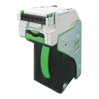
3 INSTALLATION
This section provides installation and operating
instructions for the EBA-40 Banknote Acceptor
unit. The information within this section contains
the following features:
• Installation Procedure
• Lock Installation
• DIP Switch Configuration
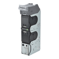
Installation Procedure
The EBA-40 Frame Unit provides installation holes
for each surface.
E
NTIRE
U
NIT
I
NSTALLATION
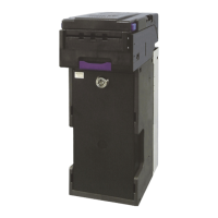
Perform the following steps to install the EBA-40
Unit:
1. Place the EBA-40 Unit Frame in its intended
mounting location.
2. Bolt the bottom side of the EBA-40 Frame into its
in
tended location using four (4) M3 Screws
(See Figure 7 a
1
through a
4
) from the outside of
the Frame when this mounting configuration is
preferred.
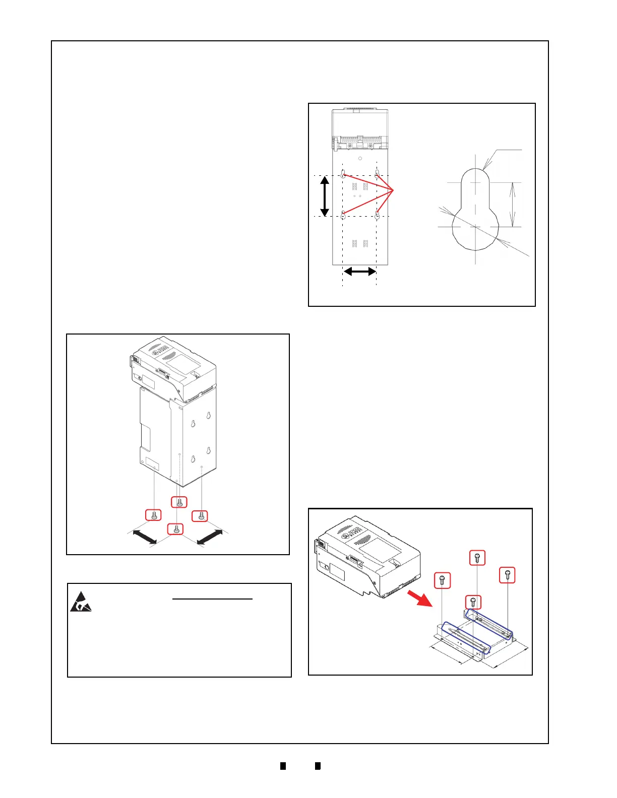
3. Hang the EBA-40 Frame onto shafts which fit in
place for
the proper width and length of the Key
Hole Slots on the rear side of the Frame when this
mounting configuration is preferred (See Figure
8).
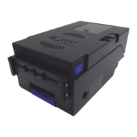
A
CCEPTOR
H
EAD
I
NSTALLATION
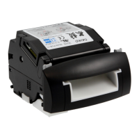
Perform the following steps to install the EBA-40
Acceptor Head Assembly using the Mounting
Bracket:
1. Place the EBA-40 Acceptor Head in its intended
mounting location.
2. Install the Mounting Bracket into its intended
lo
cation using four (4) M4x6 Screws (See Figure
9 a
1
through a
4
) provided with the Mounting
Bracket.
3. Slide and install the EBA-40
Acceptor Head
Assembly (See Figure 9 b) onto the Mounting
Bracket while simultaneously sliding the “Ped-
estal Rail
” (See Figure 9 c
1
& c
2
) in place when
this mounting configuration is preferred.
84mm
60mm
50mm
a
1
a
2
a
3
a
4
84mm
60mm
50mm
a
1
a
2
a
3
a
4
60mm
50mm
a
1
a
2
a
3
a
4
Figure 7 M3 Screw Locations (Bottom)
WARNING: The maximum length of the
M3 Screws should be selected
considering the Cabinet or Mounting
Bracket thickness. The Mounting
Screws’ length should not extend more
than 8mm upward from the bottom of
the SD3 Stacker Box Frame.
Key
84mm
Ø6
Ø
1
0
74mm
Rear View
9.5mm
Hole Slots
Figure 8 Key Hole Slot Locations (Rear)
Figure 9 M4 Screw Locations (Rear & Bottom)