P/N 960-000173R_Rev. A {EDP #229278} © 2013, JAPAN CASH MACHINE CO., LTD.
EBA
®
Series Banknote Acceptor (EBA-40) Integration Guide
CONNECTOR PIN ASSIGNMENTS (Continued 3)
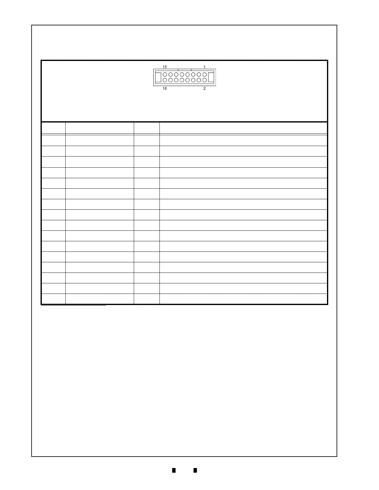
Table 13 lists the EBA-40 Photo-Coupler Interface Pin Assignments.
Table 13 EBA-40 Photo-Coupler Interface Pin Assignments
Header: XG4C-1634 (OMRON)
Housing: XG5M-1635-N Slit Wire (OMRON)
Recommended Wire: UL1007 AWG#26-28
OR
Housing: XG4M-1630-T Flat Cable (OMRON)
Recommended Wire: UL2651 AWG#28
Pin No. Signal Name
I/O
*
*. I/O (input/output) is the terminal as viewed from the Banknote Acceptor’s backside.
Function
1 +12V/+24V -
Power Supply
2 GND
-
GND
3
+12V/+24V
-
Power Supply
4 GND
-
GND
5 TTL - TXD
OUT
No Connection
6 SG
-
No Connection
7 TTL - RXD
IN
No Connection
8 ccTalk TXD/RXD
IN/OUT
No Connection
9 MDB - TXD
OUT
No Connection
10 MDB - RXD
IN
No Connection
11 MDB COM
-
No Connection
12 I/F 12V Photo-Coupler Communication Interface Power Supply 12V
13 PC - TXD
OUT
Photo-Coupler Communication Output Signal Line
14 I/F GND
-
Photo-Coupler Communication Interface GND
15 SW - IN
IN
No Connection
16 PC - RXD
IN
Photo-Coupler Communication Input Signal Line