P/N 960-000173R_Rev. A {EDP #229278} © 2013, JAPAN CASH MACHINE CO., LTD.
EBA
®
Series
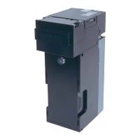
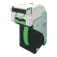
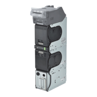
Banknote Acceptor (EBA-40)
Table of Contents
Page
1 GENERAL INFORMATION......................................................................................1
Description.......................................................................................................................... 1
EBA-40 Unit ......................................................................................................................
.. 1
Model Descriptions ............................................................................................................. 2
Type Descriptions ...............................................................................................................2
Software Descriptions......................................................................................................... 2
Precautions.......................................................................................................................
.. 2
User Cautions ................................................................................................................................. 2
Installation Cautions ..................................................................................................................... 2
Mounting, Dismounting & Transportation...................................................................................... 3
Placing Foreign Objects into the Unit
...........................................................................................3
Preventive Maintenance ..........................................................................................................
..... 3
Banknote Fitness Requirements....................................................................................................
. 4
Primary Features ................................................................................................................4
Component Names............................................................................................................. 5
2 SPECIFICATIONS....................................................................................................6
Technical Specifications ...................................................................................................... 6
Environmental Specifications .............................................................................................. 7
Electrical Specifications ...................................................................................................... 7
Structural Specifications...................................................................................................... 7
3 INSTALLATION .......................................................................................................8
Installation Procedure ......................................................................................................... 8
Entire Unit Installation ..................................................................................................................... 8
Acceptor Head Installation .............................................................................................................. 8
Lock Installation .................................................................................................................. 9
DIP Switch Configurations ................................................................................................ 10
4 CONNECTOR PIN ASSIGNMENTS ......................................................................11
CONNECTOR PIN ASSIGNMENTS (Continued 1).......................................................... 12
CONNECTOR PIN ASSIGNMENTS (Continued 2)
.......................................................... 13
CONNECTOR PIN ASSIGNMENTS (Continued 3)
.......................................................... 14
CONNECTOR PIN ASSIGNMENTS (Continued 4)
.......................................................... 15
CONNECTOR PIN ASSIGNMENTS (Continued 5)
.......................................................... 16
CONNECTOR PIN ASSIGNMENTS (Continued 6)
.......................................................... 17
5 PREVENTIVE MAINTENANCE .............................................................................18
Retrieving Banknotes........................................................................................................ 18
Clearing a Banknote Jam.................................................................................................. 18
Cleaning Procedure .......................................................................................................... 18
Sensor and Roller Cleaning Procedure ........................................................................................ 18
Sensor and Roller Locations......................................................................................................
... 19
6 STANDARD INTERFACE CIRCUIT SCHEMATICS..............................................20
STANDARD INTERFACE CIRCUIT SCHEMATICS (Continued 1)................................... 21
STANDARD INTERFACE CIRCUIT SCHEMATICS (Continued 2)................................... 22
STANDARD INTERFACE CIRCUIT SCHEMATICS (Continued 3)................................... 23
7 OPERATIONAL FLOWCHART .............................................................................24
Operational Flowchart (Continued 1)................................................................................ 25
8 TROUBLESHOOTING ...........................................................................................26
Introduction ....................................................................................................................... 26
Troubleshooting Overview ................................................................................................ 26